MIL- STD-883F 2004 TEST METHOD STANDARD MICROCIRCUITS.pdf - 第476页
MIL-STD-883F METHOD 2035 19 August 1994 4 FIGURE 2035-1. Bond area . FIGURE 2035-2. Accept able bond area . FIGURE 2035-3. Rejectabl e bond area .

MIL-STD-883F
METHOD 2035
19 August 1994
3
3.9 Reports of inspection. For class S devices, or when specified for other device classes, the manufacturer shall furnish
inspection reports with each shipment of devices. The report shall describe the results from the ultrasonic inspection, and
list the purchase order number, or equivalent identification, the part number, the date code, the quantity inspected, the
quantity rejected, and the date of the test. For each rejected device, the part number, the serial number when applicable,
and the cause for rejection shall be listed.
3.10 Acoustic micrograph and report retention
. When specified, the manufacturer shall retain a set of the ultrasonic
images and a copy of the inspection report, for the period specified.
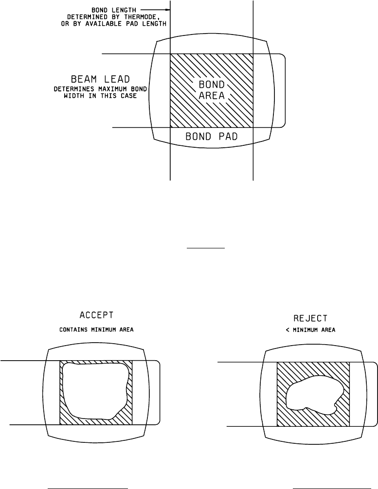
3.11 Examination and acceptance criteria
. Once the manufacturer has established the total bond area to be sought,
based upon studies of the device to be bonded, and the inclusion of a prudent excess margin, then the following shall be
considered the minimum bond area percentage:
a. In the case of solder bonds of lead-tin alloys a bond area percentage of 75 percent of the total bond area shall be
considered minimum.
b. In the case of gold-tin eutectic and gold-gold thermocompression, a bond area percentage of 50 percent of the
total bond area shall be considered minimum, except in the case of lead misalignment; when lead misalignment is
a contributing factor a bond area percentage of 75 percent shall be considered minimum.
In the examination of devices, the following aspects shall be considered unacceptable bonding, and devices which exhibit
any of the following defects shall be rejected:
a. A bond having a total bond area less than the minimum bond area. The failure may be caused by any reason,
including lateral or longitudinal misalignment.
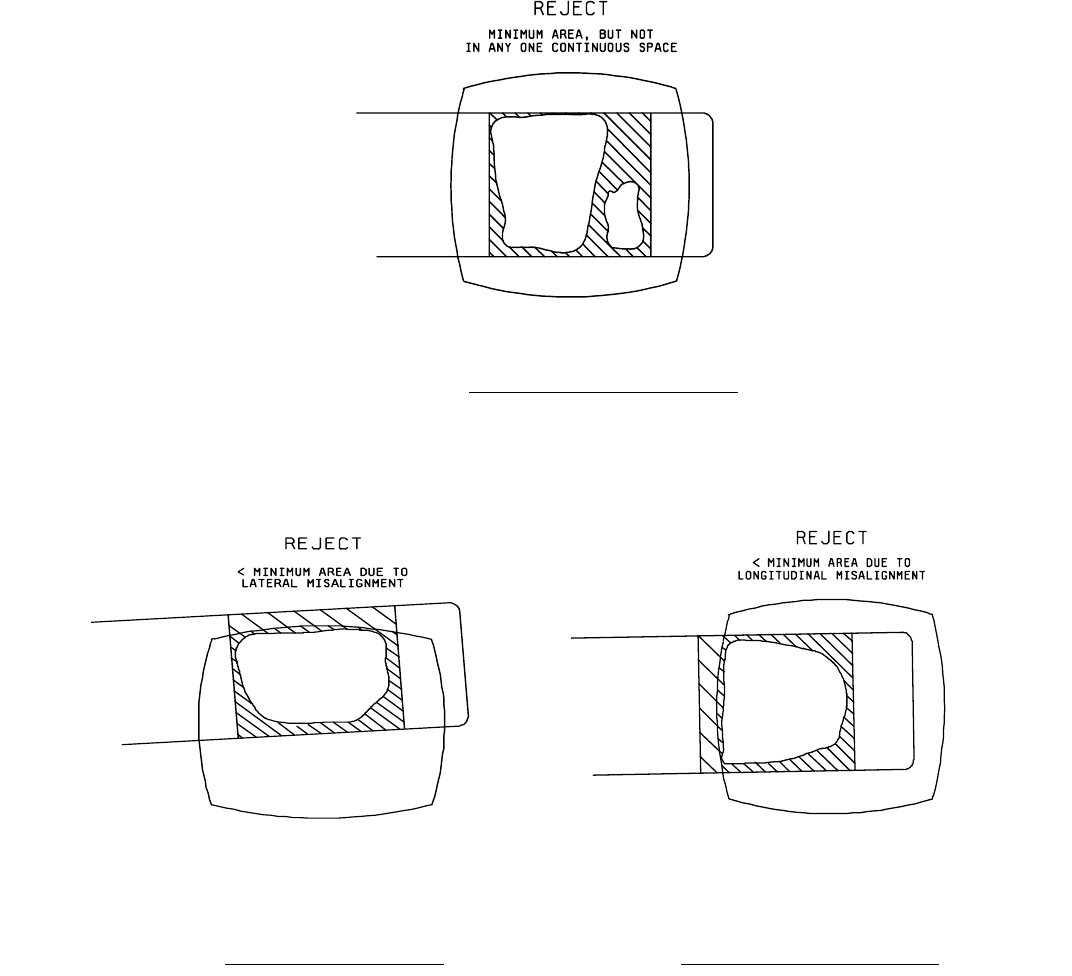
b. A bond meeting the minimum bond area, but with this area being discontinuous so that no single bonded area
meets or exceeds the minimum bond area.
4. Summary
. The following details shall be specified in the applicable acquisition document:
a. Number of views to be taken by SLAM inspection of each piece or bonding site, in accordance with 3.10, if other
than one view.
b. Markings of devices, or labeling of images, if other than in accordance with 3.2, or special markings of devices to
indicate that they have been ultrasonically imaged, if required.
c. Defects to be sought in the devices, and criteria for acceptance or rejection, if other than in 3.11.
d. Image and report retention when applicable (see 3.10).
MIL-STD-883F
METHOD 2035
19 August 1994
4
FIGURE 2035-1. Bond area
.
FIGURE 2035-2. Acceptable bond area
. FIGURE 2035-3. Rejectable bond area.
MIL-STD-883F
METHOD 2035
19 August 1994
5
FIGURE 2035-4. Rejectable discontinuous bond area
.
FIGURE 2035-5. Lateral misaligned bond area
. FIGURE 2035-6. Longitudinal misaligned bond area.
*