MIL- STD-883F 2004 TEST METHOD STANDARD MICROCIRCUITS.pdf - 第300页
MIL-STD-883F METHOD 2017.8 18 June 2004 10 Class H Class K 3.1. 4 Separati on . Element s shal l not overhang t he edge of the s ubstr ate. A mi nimum cl earance of 1.0 mil s hall be maintained bet ween any uninsul ated …
MIL-STD-883F
METHOD 2017.8
18 June 2004
9
Class H Class K
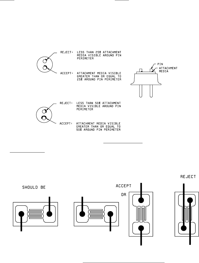
i. For element connection to a package post lead, attachment media visible for less than 25 percent of the post
perimeter. When the post also serves for substrate attachment, media shall be visible for no less than 50 percent
of the post perimeter. (see Figure 2017-3C)
j. Cold solder joints.
k. For thin film NiCr only, nonconductive adhesive material that covers more than 10 percent of the active area of
deposited resistor material.
FIGURE 2017-3c. Package Post Criteria
.
3.1.3 Element orientation
. Element not located or oriented in accordance with the applicable assembly drawing of the
device. Elements whose bond and electrical configuration is symmetrical may be rotated unless otherwise stated in the
assembly drawings.
FIGURE 2017-3d. Acceptable Symmetrical Element Orientation.
MIL-STD-883F
METHOD 2017.8
18 June 2004
10
Class H Class K
3.1.4 Separation
. Elements shall not overhang the edge of the substrate. A minimum clearance of 1.0 mil shall be
maintained between any uninsulated portion of the element and any non-common conductive surface.
3.1.5 Bond inspection, magnification 30X to 60X
. This inspection and criteria shall be the required inspection for the bond
type(s) and location(s) to which they are applicable when viewed from above.
Note: Wire tail shall not be considered part of the bond when determining physical bond dimensions.
3.1.5.1 Ball bonds
. No device shall be acceptable that exhibits:
a. Ball bond diameter less than 2.0 times or greater than 5.0 times the wire diameter.
b. Ball bonds where the wire exit is not completely within the periphery of the ball.
c. Ball bonds where the wire center exit is not within the boundaries of the bonding site.
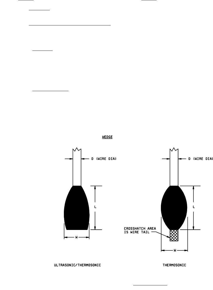
3.1.5.2 Wire wedge bonds
. No device shall be acceptable that exhibits: (see Figure 2017-4a)
a. Ultrasonic and thermosonic wedge bonds that are less than 1.0 times or greater than 3.0 times the wire diameter in
width or less than 0.5 times the wire diameter in length or no evidence of tool impression.
b. Devices with thermocompression wedge bonds that are less than 1.2 times or greater than 3.0 times the wire
diameter in width or less than 0.5 times the wire diameter in length or no evidence of tool impression.
FIGURE 2017-4a. Bond Dimensions
.
*
MIL-STD-883F
METHOD 2017.8
18 June 2004
11
Class H Class K
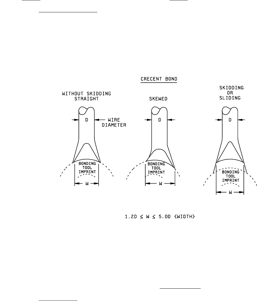
3.1.5.3 Tailless bonds (crescent)
. No device shall be acceptable that exhibits:
a. Tailless bonds that are less than 1.2 times or greater than 5.0 times the wire diameter in width. (see Figure
2017-4b).
b. A tailless bond of a gold wire bonded on the aluminum pads of a die.
FIGURE 2017-4b. Bond Dimensions
.
3.1.5.4 Compound bond
. No device shall be acceptable that exhibits the following:
NOTE: Broken or lifted bonds as a result of electrical troubleshooting or tuning shall be considered rework and shall not
apply to the 10 percent repair limitation.
*