MIL- STD-883F 2004 TEST METHOD STANDARD MICROCIRCUITS.pdf - 第359页
MIL-STD-883F METHOD 2020.8 18 June 2004 3 3.3.2 Tes t monitor ing . Eac h tes t cyc le (s ee 3.3) s hall be c ontinuous ly monit ored, except for t he period duri ng co- test shocks and 250 ms maximum af ter the s ho cks…

MIL-STD-883F
METHOD 2020.8
18 June 2004
2
3.2.2 Detection system checkout. With the shaker deenergized, the STU transducer shall be mounted face-to-face and
coaxial with the PIND transducer using the attachment medium used for testing the devices. The STU shall be activated
several times to verify low level signal pulse visual and threshold detection on the oscilloscope. Not every application of the
STU will produce the required amplitude. All pulses which are greater than 20 mV shall activate the detector.
3.2.3 System noise verification
. System noise will appear as a fairly constant band and must not exceed 20 millivolts
peak to peak when observed for a period of 30 to 60 seconds.
3.3 Test sequence
. The following sequence of operations (a through i) constitute one test cycle or run.
a. 3 pre-test shocks.
b. Vibration 3 ±1 seconds.
c. 3 co-test shocks.
d. Vibration 3 ±1 seconds.
e. 3 co-test shocks.
f. Vibration 3 ±1 seconds.
g. 3 co-test shocks.
h. Vibration 3 ±1 seconds.
i. Accept or reject.
3.3.1 Mounting requirements
. Special precautions (e.g., in mounting, grounding of DUT leads, or grounding of test
operator) shall be taken as necessary to prevent electrostatic damage to the DUT.
Batch or bulk testing is prohibited.
Most part types will mount directly to the transducer via the attachment medium. Parts shall be mounted with the
largest flat surface against the transducer at the center or axis of the transducer for maximum sensitivity. The DUT
shall be placed such that the geometric center of the surface contacting the transducer is centrally located on the
transducer to within approximately 2 mm of the transducer surface’s geometric center. Where more than one large
surface exists, the one that is the thinnest in section or has the most uniform thickness shall be mounted toward the
transducer, e.g., flat packs are mounted top down against the transducer. Small axial-lead, right circular cylindrical
parts are mounted with their axis horizontal and the side of the cylinder against the transducer. Parts with unusual
shapes may require special fixtures. Such fixtures shall have the following properties:
(1) Low mass.
(2) High acoustic transmission (aluminum alloy 7075 works well).
(3) Full transducer surface contact, especially at the center.
(4) Maximum practical surface contact with test part.
(5) No moving parts.
(6) Suitable for attachment medium mounting.
*
*

MIL-STD-883F
METHOD 2020.8
18 June 2004
3
3.3.2 Test monitoring. Each test cycle (see 3.3) shall be continuously monitored, except for the period during co-test
shocks and 250 ms maximum after the shocks. Particle indications can occur in any one or combinations of the three
detection systems as follows:
a. Visual indication of high frequency spikes which exceed the normal constant background white noise level.
b. Audio indication of clicks, pops, or rattling which is different from the constant background noise present with no
DUT on the transducer.
c. Threshold detection shall be indicated by the lighting of a lamp or by deflection of the secondary oscilloscope trace.
3.4 Failure criteria
. Any noise bursts as detected by any of the three detection systems exclusive of background noise,
except those caused by the shock blows, during the monitoring periods shall be cause for rejection of the device. Rejects
shall not be retested except for retest of all devices in the event of test system failure. If additional cycles of testing on a lot
are specified, the entire test procedure (equipment setup and checkout mounting, vibration, and co-shocking) shall be
repeated for each retest cycle. Reject devices from each test cycle shall be removed from the lot and shall not be retested
in subsequent lot testing.
3.5 Screening lot acceptance
. Unless otherwise specified, the inspection lot (or sublot) to be screened for lot acceptance
shall be submitted to 100 percent PIND testing a maximum of five times in accordance with condition A herein. PIND
prescreening shall not be performed. The lot may be accepted on any of the five runs if the percentage of defective devices
in that run is less than 1 percent and the cumulative number of defective devices does not exceed 25 percent. All defective
devices shall be removed after each run. Resubmission is not allowed.
*
MIL-STD-883F
METHOD 2020.8
18 June 2004
4
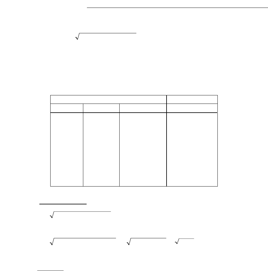
TABLE I. Package Height vs.Test Frequency for 20g Acceleration (condition A).
Note: The shaker drive test frequency (F) for condition A (see 3.1) is determined by the package internal cavity height
using the following formula:
F =
)]0511.0()/[(20 XD
where: D = Average internal package height (in inches).
20 is a constant in this application and is equal to sinusoidal acceleration of 20g.
F is the shaker drive test frequency (in Hz)
Based on the formula above, the following table is generated:
Average Internal Cavity Height Test Frequency
Mils mm inches Hz
30 0.76 0.030 114
40 1.02 0.040 99
50 1.27 0.050 88
60 1.52 0.060 81
70 1.78 0.070 75
80 2.13 0.080 70
90 2.29 0.090 66
100 2.54 0.100 63
110 2.79 0.110 60
Example calculation:
Assume an average internal cavity height of 70 Mils.
F =
)]0511.0()/[(20 XD
D = 70 Mils converted to inches = .070 inches.
F =
])0511.0()070/[(.20 X
=
]00358/[.20
=
5586
= 75 Hz
4. SUMMARY
. The following details shall be specified in the applicable acquisition document:
a. Test condition letter A or B.
b. Lot acceptance/rejection criteria (if other than specified in 3.5).
c. The number of test cycles, if other than one.
d. Pre-test shock level and co-test shock level, if other than specified.
*