MIL- STD-883F 2004 TEST METHOD STANDARD MICROCIRCUITS.pdf - 第189页
MIL-STD-883F METHOD 2004.5 29 November 1985 3 TEST CONDITION B 2 - LEAD FATIGUE 1. PURPOSE . This test is des igned to c heck the res ist ance of t he leads t o metal fat igue. 2. APPARATUS . Att aching devi ces, clamps …

MIL-STD-883F
METHOD 2004.5
29 November 1985
2
3. PROCEDURE
. Each lead or terminal to be tested shall be subjected to force sufficient to bend the lead as specified in
3.1 through 3.5, as applicable. Any number or all of the leads of the test device may be bent simultaneously. Rows of leads
may be bent one row at a time. Each lead shall be bent through one cycle as follows: Bend through the specified arc in one
direction and return to the original position. All arcs shall be made in the same plane without lead restriction.
3.1 Direction of bends
. Test leads shall be bent in the least rigid direction. If there is no least rigid direction, they may be
bent in any direction. No lead shall be bent so as to interfere with another lead. If interference is unavoidable, the test lead
shall be bent in the opposite direction to the angle specified and returned to its normal position.
3.2 Procedure for initial conditioning of formed leads
. When normally straight leads are supplied in a formed condition
(including the staggered lead dual-in- line configuration), the lead forming operation shall be considered acceptable initial
conditioning in place of that specified, provided the lead forming has been done after lead plating and the forming is at least
as severe in permanent lead deformation as the specified bending.
3.3 Procedure for flexible and semi-flexible leads (e.g., flat packs and axial-lead metal-can devices)
.
3.3.1 Flexible leads
. A lead shall be considered flexible if its section modulus (in the least rigid direction) is less than or
equal to that of a rectangular lead with a cross section of 0.15 x 0.51 mm (.006 x .020 inch). Round leads less than or equal
to 0.51 mm (.020 inch) in diameter shall be considered flexible. Flexible leads shall be bent through an arc of at least 45°
measured at a distance 3.05 ±.76 mm (0.120 ±0.03 inch) along the lead from the seal unless otherwise specified.
3.3.2 Semi-flexible leads
. Semi-flexible leads are those leads with a section modulus (in the least rigid direction) greater
than that of a rectangular lead with a cross section of 0.15 x 0.51 mm (0.006 x 0.020 inch) which are intended to be bent
during insertion or other application. Round leads greater than 0.51 mm (.020 inch) diameter shall be considered
semi-flexible except as noted in 3.5. Semi-flexible leads shall be bent through an arc of at least 30° measured at the lead
extremities unless otherwise specified.
3.4 Procedure for dual-in-line and pin grid array package leads
. Dual-in-line package leads are leads with more than one
section modulus, with leads normally aligned in parallel at a 90° angle from the bottom of the package during insertion.
Dual-in-line package leads shall be bent inward through an angle sufficient to cause the lead to retain a permanent bend
(i.e., after stress removal) of at least 15°. For configuration 1 and 2, the angle of bend shall be measured from the lead
extremities to the first bend (see figure 2004-1), For configuration 3, the angle of bend shall be measured from the lead
extremities to the seating plane (see figure 2004-1). Pin grid array packages shall have the leads required for testing from
the outside row of leads on opposite sides bent through an angle sufficient to cause the lead to retain a permanent bend
(i.e., after stress removal) of at least 15°. The angle of bend shall be 15° from normal and the bend shall be made at the
approximate seating plane. At the completion of the initial bend, the leads shall be returned to their approximate original
position.
3.5 Procedure for rigid leads or terminals
. A lead or terminal shall be considered rigid if it is not intended to be flexed in
mounting, and not covered in 3.3 or 3.4. Devices with terminals complying with this description shall be subjected to a
normal mounting operation and removal, unless otherwise specified. When the normal mounting/removal operation is
destructive to the terminals (e.g., terminal weld, wire wrap), the initial conditioning need not be performed.
3.6 Failure criteria
. When examined using magnification between 10X and 20X after removal of the stress, any evidence
of breakage, loosening, or relative motion between the terminal lead and the device body shall be considered a device
failure. When specified, post-test measurements (see 4) shall be made after visual examination. When the above
procedures are used as initial conditioning in conjunction with other tests, these measurements may be conducted at the
conclusion of that test or sequence of tests.
4. SUMMARY
. The following details shall be specified in the applicable acquisition document:
a. Bending arc, if other than that specified.
b. Procedure, if other than that specified.
c. Number and selection of leads and procedure for identification, if other than that specified.
d. Post test measurements, if applicable (see 3.6)
MIL-STD-883F
METHOD 2004.5
29 November 1985
3
TEST CONDITION B
2
- LEAD FATIGUE
1. PURPOSE
. This test is designed to check the resistance of the leads to metal fatigue.
2. APPARATUS
. Attaching devices, clamps, supports, or other suitable hardware necessary to apply a repeated bending
stress through the specified bend angle.
3. PROCEDURE
. The appropriate procedure of 3.1 or 3.2 for the device under test shall be used.
3.1 Procedure for dual-in-line packages
. The leads to be tested shall be subjected to three cycles of test condition B
1
and
shall be subjected to a force sufficient to bend the leads as specified in 3.4 of condition B
1
.
3.2 Procedure for flat packages and can packages
. A force of 0.229 ±0.014 kg (8 ±0.5 ounces), unless otherwise specified,
shall be applied to each lead to be tested for three 90° ±5° arcs of the case. For leads with a preplated or prefinished section
modulus equal to or less than that of a rectangular lead with a cross section of 0.16 x 0.51 mm (0.006 x 0.020 inches) or round
leads with a cross section of 0.51 mm (0.020 inch) in diameter, the force shall be 0.085 ±0.009 kg (3 ±0.3 ounces). Section
modulus is defined as bc
2
/6 for rectangular leads, and 0.098 (φb
1
)
3
for round leads (see MIL-STD-1835). An arc is defined as
the movement of the case, without torsion, to a position perpendicular to the pull axis and return to normal. All arcs on a single
lead shall be made in the same direction and in the same plane without lead restriction. A bending cycle shall be completed in
from 2 to 5 seconds. For devices with rectangular or ribbon leads, the plane of the arcs shall be perpendicular to the flat plane
of the lead. The test shall not be applied to end leads of packages where its application will apply primarily torsion forces at the
lead seal.
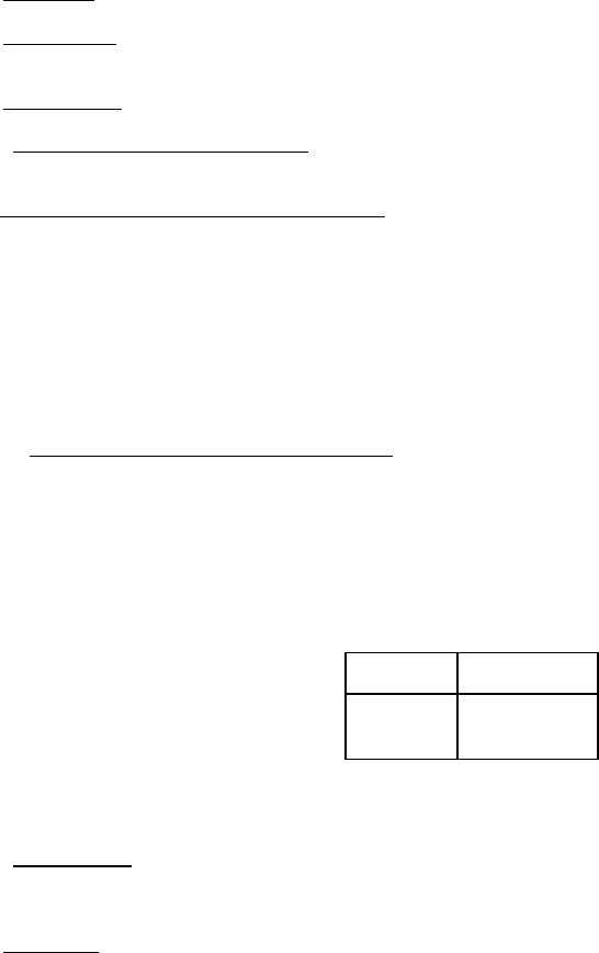
3.2.1 Optional procedure for fine pitch/small leads
. A force as determined by the following formula unless otherwise
specified, shall be applied to each lead to be tested for 90 degrees ±5 degree arcs of the device. All other conditions of section
3.2 shall apply: Weight = (area in square inches) x 2.1 % x (K psi) x 453.6 grams/lb. Where K is based on the ultimate tensile
strength (UTS) for a particular material. Typical value for kovar and alloy 42 are listed below. The UTS for other materials can
be found in vendor data sheets. The result shall be rounded to the nearest whole number.
NOTE: A lead pitch of less than or equal to 25 mils is considered fine pitch.
Material
UTS in psi
Kovar
Alloy 42
75000
71000
3.3 Failure criteria
. A broken lead on a device shall be considered a failure. When examined using magnification between
10X and 20X after removal of the stress, any device which exhibits any evidence of breakage, loosening, or relative motion
between the terminal lead and the device body shall be considered a device failure.
4. SUMMARY
. The following details shall be specified in the applicable acquisition document:
a. Force to be applied to the lead, if other than above (see 3).
b. Number of cycles, if other than above (see 3).
c. Maximum bend angle, if other than above (see 3).

MIL-STD-883F
METHOD 2004.5
29 November 1985
4
TEST CONDITION C
1
- LEAD TORQUE
1. PURPOSE
. This test is designed to check device leads (or terminals) and seals for their resistance to twisting
motions.
2. APPARATUS
. The torque test requires suitable clamps and fixtures, and a torsion wrench or other suitable method of
applying the specified torque without lead restriction.
3. PROCEDURE
. The appropriate procedure of 3.1 or 3.2 for the device under test shall be used.
3.1 Procedure for devices with circular cross-section terminals or leads
. The device body shall be rigidly held and the
specified torque shall be applied for 15 seconds minimum to the lead (terminal) to be tested, without shock, about the axis of
the lead (terminal).
3.2 Procedure for devices with rectangular cross-section terminals or leads
. The device body shall be rigidly held and a
torque of 1.45 ±.145 kg-mm (2.0 ±0.2 ounce-inch) unless otherwise specified, shall be applied to the lead (terminal) at a
distance of 3.05 ±0.76 mm (0.12 ±0.03 inch) from the device body or at the end of the lead if it is shorter than 3.05 mm (0.12
inch). The torque shall be applied about the axis of the lead once in each direction (clockwise and counterclockwise).
When devices have leads which are formed close to the body, the torque may be applied 3.05 ±0.76 mm (0.12 ±0.03 inch)
from the form. For device leads which twist noticeably when less than the specified torque is applied, the twist shall be
continued until the twist angle reaches 30° ±10° or the specified torque is achieved, whichever condition occurs first. The
lead shall then be restored to its original position.
3.3 Failure criteria
. When examined using magnification between 10X and 20X after removal of the stress, any evidence
of breakage, loosening, or relative motion between the terminal (lead) and the device body shall be considered a device
failure. When a seal test in accordance with method 1014 is conducted as a post test measurement following the lead
integrity test(s), meniscus cracks shall not be cause for rejection of devices which pass the seal test.
4. SUMMARY
. The following details shall be specified in the applicable acquisition document:
a. Torque to be applied for circular cross-section leads (see 3.1).
b. Duration of torque application for circular cross-section leads, if other than 15 seconds minimum (see 3.1).
c. Torque to be applied for rectangular cross-section leads, if other than 1.45 ±0.145 kg-mm (2.0 ±0.2 ounce-inch)
(see 3.2).
d. See general summary above.
TEST CONDITION C
2
- STUD TORQUE
1. PURPOSE
. This test is designed to check the resistance of the device with threaded mounting stud to the stress
caused by tightening the device when mounting.
2. APPARATUS
. The torque test requires suitable clamps and fixtures, and a torsion wrench or suitable method of
applying the specified torque.
3. PROCEDURE
. The device shall be clamped by its body or flange. A flat steel washer of a thickness equal to six
thread pitches of the stud being tested and a new class 2 fit steel nut shall be assembled in that order on the stud, with all
parts clean and dry. The specified torque shall be applied without shock to the nut for the specified period of time. The nut
and washer shall then be disassembled from the device, and the device then examined for compliance with the
requirements.