00191369-02.pdf - 第109页
User Manual HS-50 3 Introduction and Basic Concepts Software Version SR.501.xx 12/99 Issue US 3.2 Principles of t he Graphic User In terface 109 t I I t Abort processing 3 3 Å Clic k the cor respon ding P CB ic on . If t…
3 Introduction and Basic Concepts User Manual HS-50
3.2 Principles of the Graphic User Interface Software Version SR.501.xx 12/99 Issue US
108
t IIt
3
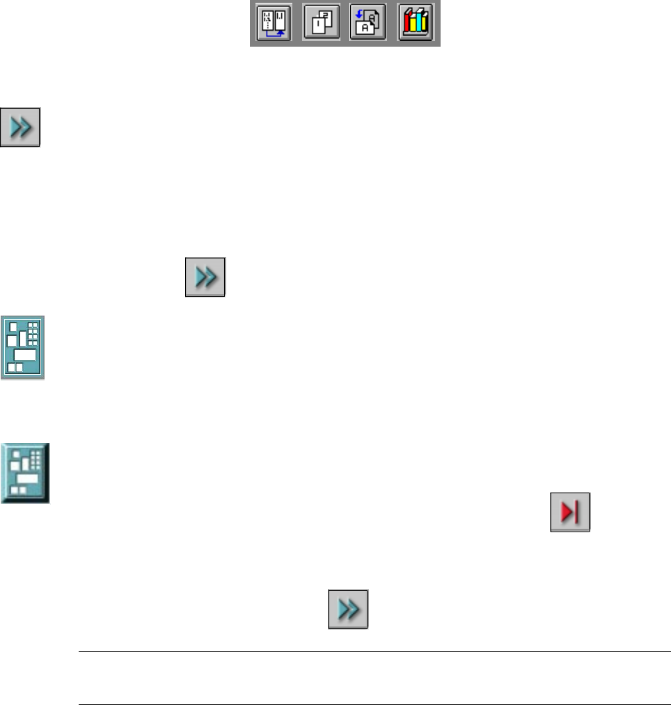
Continue processing 3
This icon is displayed after "Stop processing PCB" or after a machine stop.
(The triangles in the icon move continuously from left to right.)
Click this icon to continue the interrupted operation once the error has been successfully elimi-
nated. 3
3
Å Click the icon .
Processing is now continued.
3
Processing PCB 3
The PCB has been taken up be the system and is being processed. The PCB icon is displayed in
blue-green. 3
Processing of PCB stopped 3
If processing of the PCB has been interrupted using "Stop processing PCB"" or has been
interrupted after a fatal error or because the Stop button has been pressed, the PCB icon is again
displayed in blue-green but now has contoured edges.
3
You can continue processing by clicking
or abort it by clicking the PCB icon. 3
NOTE
The procedure used to abort processing is described below. 3
User Manual HS-50 3 Introduction and Basic Concepts
Software Version SR.501.xx 12/99 Issue US 3.2 Principles of the Graphic User Interface
109
t IIt
Abort processing 3
3
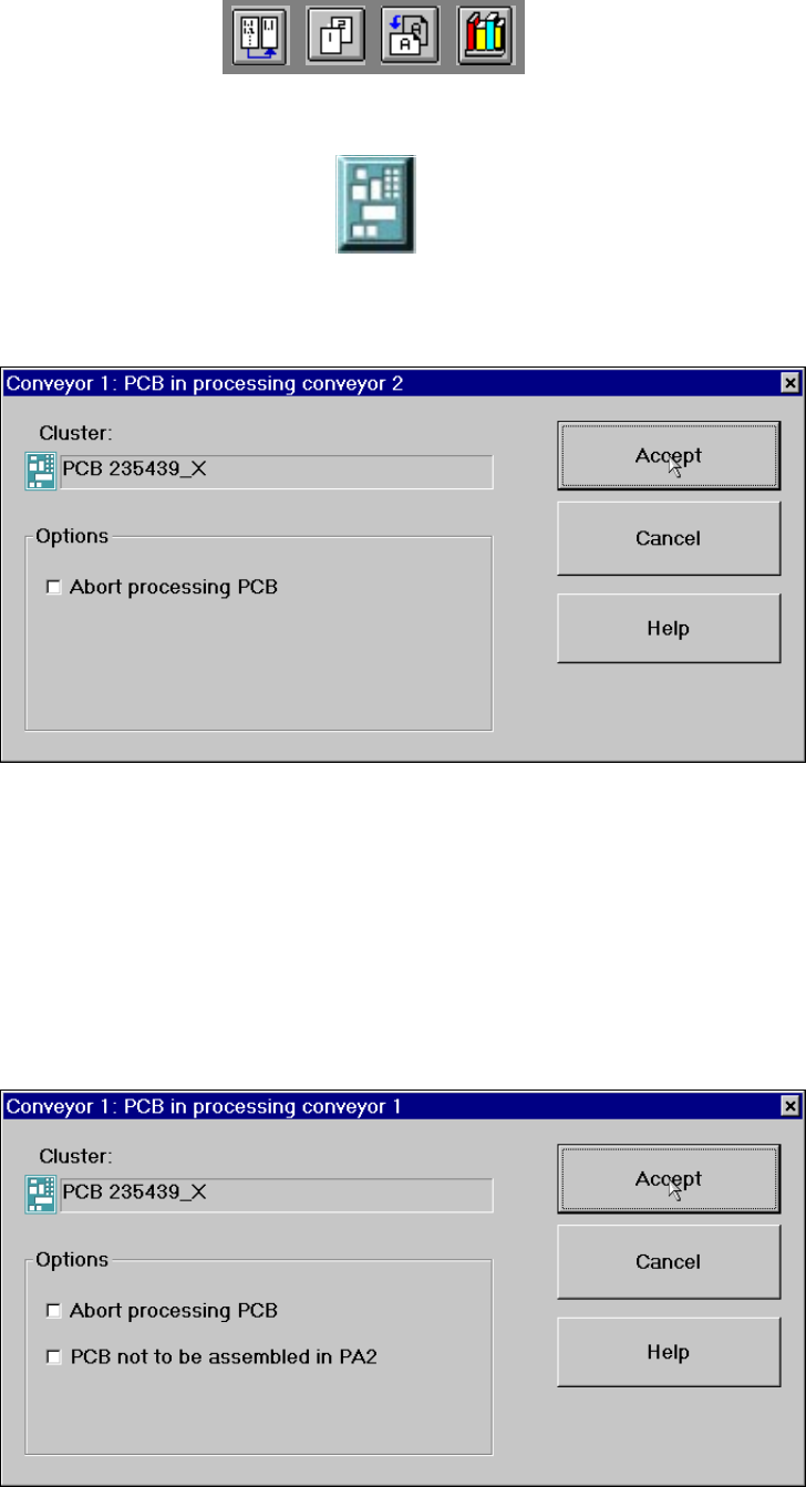
Å Click the corresponding PCB icon .
If the PCB is located on processing conveyor 2, the following dialog box is opened.
3
Å Click the checkbox "Abort processing PCB".
Å Click the Accept button.
Processing of the PCB is aborted.
The incompletely assembled PCB is transported to the output conveyor and the operator is re-
quested to remove it by hand.
If the PCB is located on processing conveyor 1, the following dialog box is opened. 3
3
3
3 Introduction and Basic Concepts User Manual HS-50
3.2 Principles of the Graphic User Interface Software Version SR.501.xx 12/99 Issue US
110
t IIt
Å Check the box "Abort processing PCB" if the PCB is to be transported to the output conveyor
without further processing.
Å Check the box "PCB not to be assembled in PA2" if the PCB is to be processed on processing
conveyor 1 and is then to be transported to the output conveyor without being processed on
processing conveyor 2.
Å Click the Accept button.
3
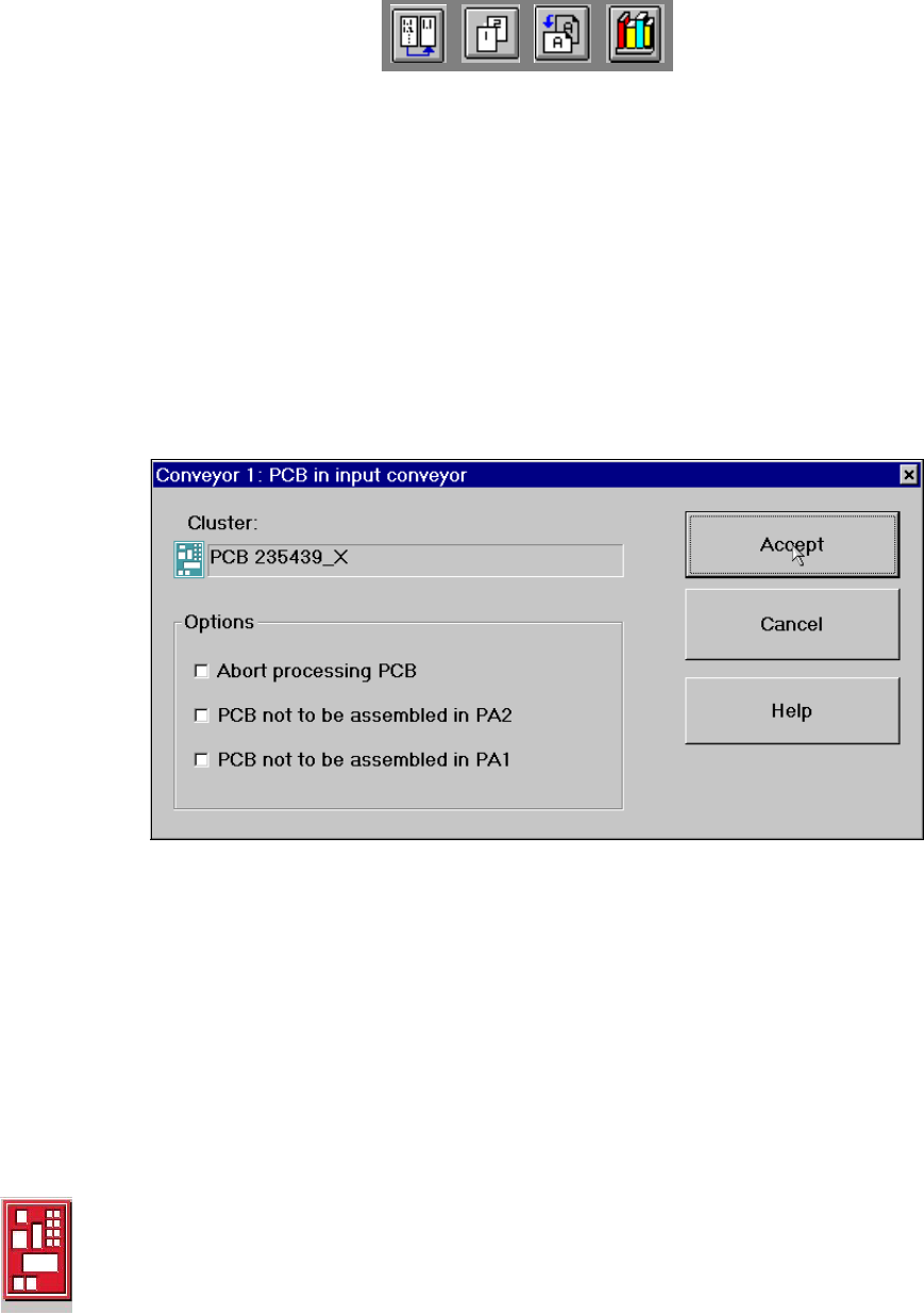
If the PCB is located on the input conveyor, the following dialog box is opened. 3
3
Å Check the box "Abort processing PCB" if the PCB is to be transported to the output conveyor
without further processing.
Å Check the box "PCB not to be assembled in PA2" if the PCB is to be processed on processing
conveyor 1 only and is then to be transported to the output conveyor without being processed
on processing conveyor 2.
Å Check the box "PCB not to be assembled in PA1" if the PCB is to be transported through pro-
cessing conveyor 1 without being processed and is then to be processed on processing con-
veyor 2.
Å Click the Accept button.
3
Processing of PCB aborted 3
If processing of the PCB has been aborted by a click on the PCB icon (see example above), the
color of the PCB icon changes to red.
The icon is also displayed in red if a PCB is manually placed on processing conveyor 1 or 2. The
PCB is not recognized by the system and is transported to the output conveyor. 3