00191369-02.pdf - 第276页
6 Vision functions User M anual HS-50 6.6 Test Component Software V ersion SR.501.xx 12/99 Issue U S 276 t I I t This menu allows you to c hange 6 – the lead di mens ions, – the packa ge dimensio ns, – t he ball i magin …
User Manual HS-50 6 Vision functions
Software Version SR.501.xx 12/99 Issue US 6.6 Test Component
275
t IIt
The GF or package form file is stored in the line computer. Basically it consists of two main parts:6
– the geometric package form data and
– the sensor-specific data.
The sensor-specific part contains 6
– the measurement conditions for the component,
– the type of lighting and
– the transformation table data.
NOTE 6
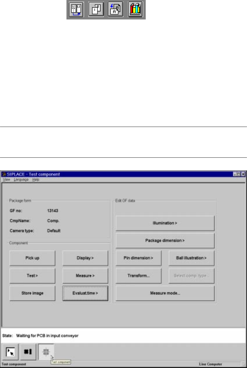
The buttons of the options of the Test component menu will only be active if you have already
loaded a package form.
6
Fig. 6.6 - 25 Test component menu, options
6 Vision functions User Manual HS-50
6.6 Test Component Software Version SR.501.xx 12/99 Issue US
276
t IIt
This menu allows you to change 6
– the lead dimensions,
– the package dimensions,
– the ball imaging parameters,
– the illumination parameters and,
– the transformation table.
6
– Lead dimension parameters are
– optical lead length in the X and Y-directions of the component
– optically lead width in the X and Y-directions of the component
NOTE 6
The pitch and number of leads can only be changed in the line computer. 6
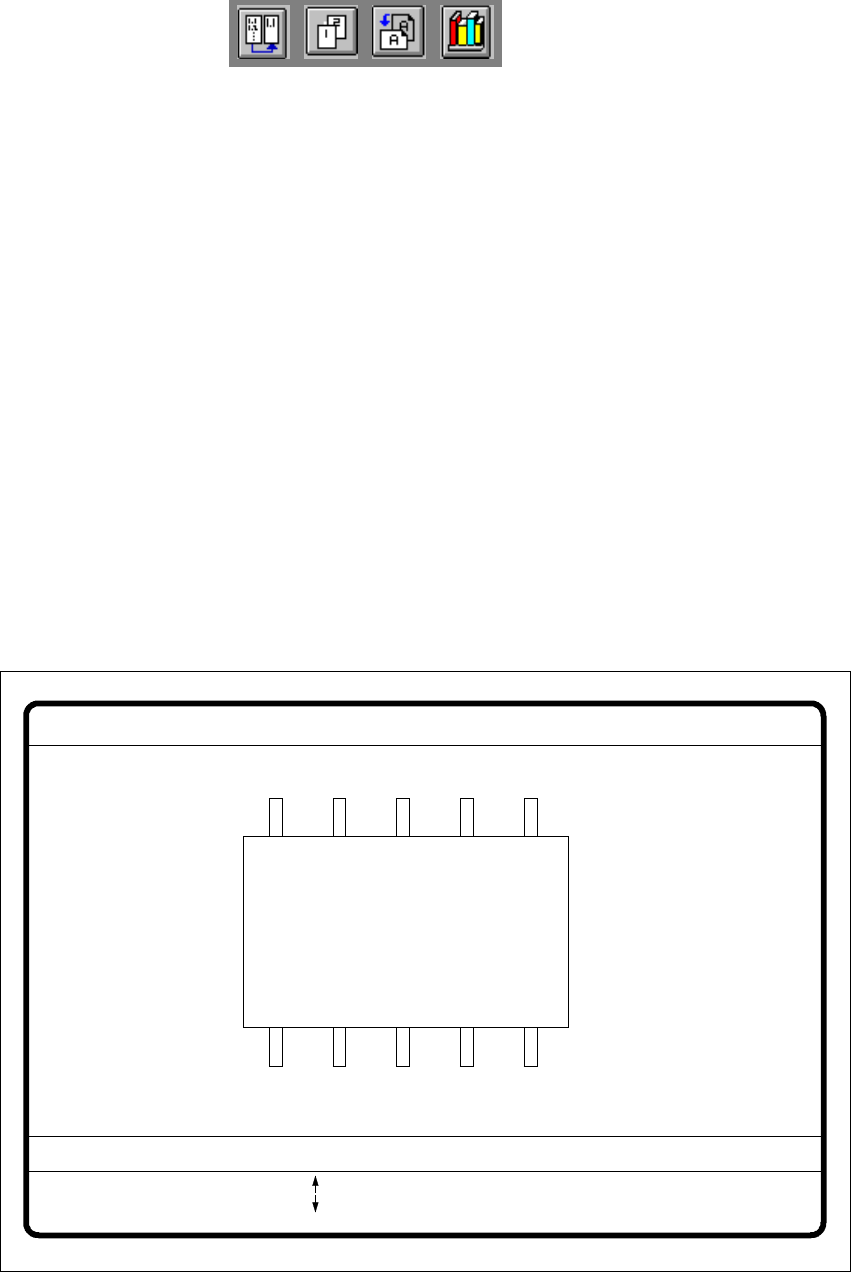
– Package dimension parameters are
– the outside dimensions of the component in millimeters in the X and Y-directions. Outside
dimensions means the optical dimensions of the component including the lead dimensions.
The geometric dimensions of the leads and component are stored in the GF file in the line
computer. Depending on the geometry of the component and on its illumination by the com-
ponent camera, it is possible that imaging errors may occur. The image does not reproduce
the life-size geometric dimensions but reduces them. This is what is called imaging reduc-
tion. For this reason one refers to the optical dimensions of the leads and component. Set
the component dimensions in a way that they match the visible component outline. The re-
duction factor is entered in the "Real-MA" file. 6
As regards defining the position of the origin of the coordinates system and defining regular and
irregular components, please refer to Section 6.3.2
on page 198. 6
– Ball imaging parameters are
– inner and outer radius type
– inner and outer radius (usually not used)
–contrast
– ball model
User Manual HS-50 6 Vision functions
Software Version SR.501.xx 12/99 Issue US 6.6 Test Component
277
t IIt
– Illumination parameters are
– the contrast in the image
– the X plane, flat, middle and steep illumination levels for illuminating the component
(brightness control).
– Color representation parameters (5 sections)
– 10 parameter IN values
– 10 parameter OUT values
The parameters are stored in the GF file in the line computer. Upon request the GF file will be sent
to the station computer. Finally it will be converted and transferred to the MVS controller. 6
If you modify a parameter, it will be entered in the x.SST file. The x.SST file will be converted and
loaded into the MVS controller. 6
6.6.4.8 Illumination Option
When this option is selected the video image for checking and setting illumination will appear. 6
6
Fig. 6.6 - 26 Test component menu, Illumination video image
6
GF No. = 5Illumination
RET: Test component
Illuminat. = flat/middle/steep Field step =
Blank: step width
Tab: Illumination
Brightness = 0 ... 255
: Brightness up
: Brightness down