00191369-02.pdf - 第26页
1 Introduction User Manual HS-50 1.7 Connection data for the plac ement system Software Version SR.501.xx 12/99 Issue U S 26 t I I t 1.7 Connection dat a for the placement system 1.7.1 Electrical and pneumatic connection…
User Manual HS-50 1 Introduction
Software Version SR.501.xx 12/99 Issue US 1.6 The line concept
25
t IIt
1.6 The line concept
1.6.1 Overview
The placement system can be linked to input and output stations, screen printing systems, sol-
dering ovens and other automatic placement systems from the SIPLACE range (S-20, F4, F5
and the SIPLACE G glue application station). All SIPLACE modules are supplied with the neces-
sary data by the UNIX line computer. The placement system can also be linked to a higher level
data processing system through the use of suitable interfaces.
1.6.2 Technical data - line concept
* SIPLACE HS-50, SIPLACE 80 S-20 or SIPLACE 80 F4 with 12-segment revolver head
** SIPLACE 80 F4 / F5
1
System SIPLACE placement lines
Module
SIPLACE HS-50 / SIPLACE 80 S-20/
SIPLACE 80 F4 / SIPLACE 80 F5
Peripherals
Input/output stations
Screen printers
Soldering ovens
Inspection stations, etc.
Range of components From 0402 * to 55 mm x 55 mm **
PCB conveyor Automatic width adjustment
PCB format 50 mm x 50 mm to 368 mm x 460 mm
Placement speed
Depends on how the modules are connected to one
another
Space required
4 m² / SIPLACE 80 modules
7.5 m² / SIPLACE HS-50 modules
1 Introduction User Manual HS-50
1.7 Connection data for the placement system Software Version SR.501.xx 12/99 Issue US
26
t IIt
1.7 Connection data for the placement system
1.7.1 Electrical and pneumatic connection points on the placement system
1
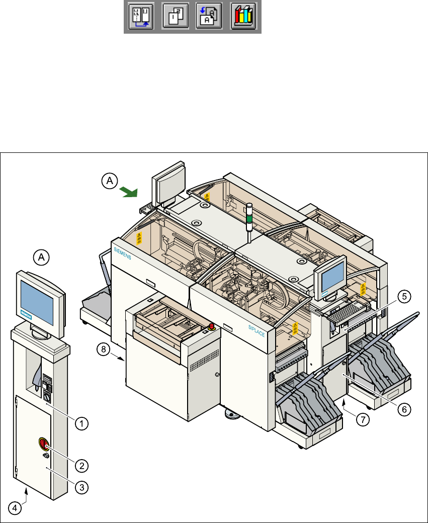
Fig. 1.7 - 1 Electrical and pneumatic connection points on the placement system
(1) Operating panel, left
(2) Main switch
(3) Safety doors to the power supply unit
(4) Hole for the power cable
(5) Operating panel, right
(6) Safety doors to the compressed air unit
(7) Hole for the compressed air line
(8) LAN connection on the station computer
User Manual HS-50 1 Introduction
Software Version SR.501.xx 12/99 Issue US 1.7 Connection data for the placement system
27
t IIt
DANGER
The placement system is supplied with 3 x 204 V AC (US version), 3 x 230 V AC, 3 x 380 V AC,
3 x 400 V AC or 3 x 415 V AC ± 5 %, 50/60 Hz mains voltage. This means that some parts of the
system carry potentially lethal voltages - even when switched off at the main switch. Incorrect han-
dling of the placement system can therefore result in death or severe injury or considerable dam-
age to equipment. 1
WARNING
NEVER detach compressed air lines while they are still pressurized. Risk of injury. 1
1.7.2 Technical data - electrical ratings
1
Supply voltage
3 x 204 VAC ± 5 %; 50/60 Hz (U.S.A)
3 x 230 VAC ± 5 %; 50/60 Hz
3 x 380 VAC ± 5 %; 50/60 Hz
3 x 400 VAC ± 5 %; 50/60 Hz (Europa)
3 x 415 VAC ± 5 %; 50/60 Hz
Fuses
3 x 32 A (3 x 204 VAC)
3 x 32 A (3 x 230 VAC)
3 x 16 A (3 x 380 VAC)
3 x 16 A (3 x 400 VAC)
3 x 16 A (3 x 415 VAC)
Total connected load 11.1 kVA
Total output 9 kW
Power failure max. 10 msec