00191369-02.pdf - 第316页
6 Vision functions User M anual HS-50 6.7 Guidelines for Desc ribing Package Forms Software Version SR .501.xx 12 /99 Issue U S 316 t I I t 6.7.6.5 T esting Illumination Sett ings Y ou can set th e illum inatio n parame …
User Manual HS-50 6 Vision functions
Software Version SR.501.xx 12/99 Issue US 6.7 Guidelines for Describing Package Forms
315
t IIt
6
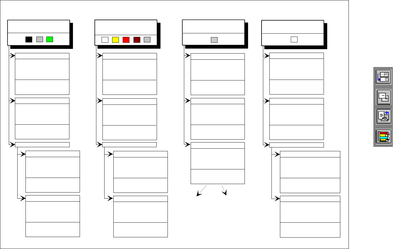
Fig. 6.7 - 8 Illumination parameters for other components at the 12x revolver head camera
Adjusting the illumination of other components
Light and dull body
( white, yellow, red, brown, grey,
metallic dull )
Ceramic body
Dark and dull body
( black, blue, green )
Reflective body
(independently of color and material)
Dull leads
flat: 70
middle: 60
steep: 150
Visual separation between leads
and body is not possible.
Illuminate body and leads equally.
Measure outline.
Shiny leads
Clear separation
between leads
and body.
Dull leads
flat: 150
middle: 120
steep: 0 - 20
Shiny leads
1. Illuminate body and leads equally.
Measure outline.
2. Trick: Use flat and middle levels to
bring leads image to saturation.
Measure.
Clear separation
between leads
and body.
for variant 2: flat: 150 - 255
middle: 60 - 150
steep: 0 - 20
flat: 200
middle: 80
steep: 0 - 20
flat: 120
middle: 80
steep: 0 - 20
Clear separation
between leads
and body.
Clear separation
between leads
and body.
J-Lead ( PLCC ), convex-type leads
Gullwing leads ( SO, QFP )
Dull leads
Shiny leads
flat: 120
middle: 50
steep: 170
flat: 170
middle: 50
steep: 120
Clear separation
between leads
and body.
Clear separation
between leads
and body.
J-Lead ( PLCC ), convex-type leads
Gullwing leads ( SO, QFP)
flat: 170
middle: 50
steep: 120
flat: 80
middle: 40
steep: 120
Clear separation
between leads
and body.
Clear separation
between leads
and body.
Other lead shapes
Dull leads
flat: 170
middle: 50
steep: 120
Visual separation between leads
and body is not generally possible.
Shiny leads
flat: 0
middle: 0 - 10
steep: 100 - 255
Clear separation
between leads
and body.
flat: 0
middle: 0 - 10
steep: 150 - 255
Leads:
Outline:
Measuring method:
Visual separation between leads
and body is not possible.
Illuminate body and leads equally.
Measure outline.
flat: 170
middle: 50
steep: 120
Visual separation between leads
and body is not possible. Measure
outline or lead tips. Leads are
outside the body.
flat: 80
middle: 40
steep: 120
J-Lead ( PLCC ), convex-type leads
Gullwing leads ( SO, QFP )
Other lead shapes
Convex-type leads
flat: 70
middle: 60
steep: 150
Other lead shapes
flat: 0
middle: 0 - 20
steep: 200 - 255
Visual separation between leads
and body is not generally possible.
Illuminate body and leads equally.
Measure outline.
Illumination level Brightness
6 Vision functions User Manual HS-50
6.7 Guidelines for Describing Package Forms Software Version SR.501.xx 12/99 Issue US
316
t IIt
6.7.6.5 Testing Illumination Settings
You can set the illumination parameters by calling the ’Illumination’ option (see Section 6.6.4.8 on
page 277
). Using the ’Measure Component Option’ on page 263 you can then measure the com-
ponent and check your settings with the aid of the measurement results. 6
Proceed as follows to test your illumination setting: 6
Å Using the illumination values suggested in Figures 6.7 - 7 or 6.7 - 8 carry out measurement.
Measurement should run through successfully.
Å For each level reduce the set brightness level by 50 %.
Measurement should run through successfully.
Å For each level raise the set brightness level by 50 %.
Measurement should run through successfully.
If you are not successful with the above procedure, proceed as follows: 6
Å Starting with the suggested illumination value, increase the brightness of each individual illu-
mination level for as long as measurement is still successful.
Å Find this upper limit value for each individual illumination level in turn.
Å Starting with the suggested illumination value, decrease the brightness of each individual illu-
mination level for as long as measurement is still successful. Find this lower limit value for each
individual illumination level in turn.
Å Determine the average value of the upper and lower limit values. This will be the optimum illu-
mination value.
Example of an illumination test: 6
– Settings from the diagram:
flat: 170
middle: 60
steep: 120
– Measure the component. Measurement is successful.
– Reduce setting values by 50%.
flat: 85
middle: 30
steep: 60
– Increase setting values by 50%.
flat: 255
middle: 90
steep: 180
User Manual HS-50 6 Vision functions
Software Version SR.501.xx 12/99 Issue US 6.7 Guidelines for Describing Package Forms
317
t IIt
– Measure the component. Measurement is successful.
– Reset the settings to the suggested values:
flat: 170
middle: 60
steep: 120
© optimum setting
NOTE 6
With respect to 0402 and 0603 components, avoid the nozzle being displayed during imaging. If
this seems likely, remove the component from the nozzle and use the ’Illumination Option
’ (see
page 277 to see whether the nozzle did appear in the image.
6.7.6.6 General Information on Setting Illumination Values
– As a rule it is better to overilluminate the component than to underilluminate it. A saturated im-
age is preferable to a low-contrast image.
– Optimum illumination is attained when only the leads are imaged and the component body is
not shown.
– If you cannot clearly separate the image of the component body from the leads, we recom-
mend to illuminate body and leads equally and then to measure the outline.