00191369-02.pdf - 第63页
User Manual HS-50 2 Operational Safety Software Version S R.501.xx 12/99 Issue US 2.1 Safety instructions 63 t I I t Å Swiv el the component table hand le up. Th e latchi ng dis k will a lso swi vel up. 3/($6( 127( ,I…
2 Operational Safety User Manual HS-50
2.1 Safety instructions Software Version SR.501.xx 12/99 Issue US
62
t IIt
2
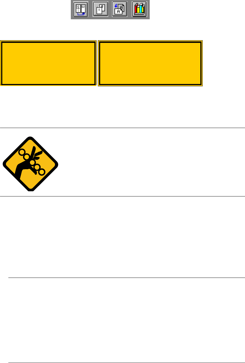
Fig. 2.1 - 5 Label: Laser radiation
6DIHW\LQVWUXFWLRQVIRUFKDQJLQJWKHKHL JKWRIFRPSRQHQWWDEOH V
WARNING 2
The component table must only be converted to modify the default
height by trained Service personnel.
Act with considerable care during the conversion process since
the system contains large weights or compression springs (potential
energy).
&RQYHUWLQJWKHFRPSRQHQWWDEOHWRVXLWDGLIIHUHQWOLQHKHLJKW
Å Use the placement system’s pneumatic controller to raise the table bed. Then insert a 120mm
spacer block between the table bed and cross-beam, and lower the bed onto the block.
Å Dismantle the internal paneling.
Å Swivel the handle down. The latching disk swivels down as well.
Å Set the screw to the desired dimension and lock in place with the locknut.
3/($6(127(
,I\RXFDQQRWORRVHQWKHDGMXVWLQJVFUHZIDUHQRXJKWKHFURVVEHDPPX VWEHUDLVHG
Å )L[WKHOLIWLQJGHYLFHWRWKHFURVVEHDP
Å &DUHIXOO\RSHQWKHFURVVEHDPFODPS
Å 5DLVHWKHFURVVEHDPXQWLOWKHHQGRIWKHWXEHSURMHFWVDSSUR[PPRXWRIWKHFODPS
Å 7LJKWHQWKHFURVVEHDPFODPS
Å 7KHQWXUQWKHDGMXVWLQJVFUHZWRWKHGHVLUHGGLPHQVLRQDQGORFNLQSODFHZLWKWKHORFNQXW
Laser radiation
Do not look into beam
Class 2 laser product
$WWHQWLRQ
/DVHUUDGLDWLRQLIWKHFRYHU
LVRSHQHGDQGWKHVDIHW\
LQWHUORFNLVE\SDVVHG
'RQRWORRNLQWREHDP
User Manual HS-50 2 Operational Safety
Software Version SR.501.xx 12/99 Issue US 2.1 Safety instructions
63
t IIt
Å Swivel the component table handle up. The latching disk will also swivel up.
3/($6(127(
,I\RXFDQQRWVZLYHOWKHODWFKLQJGLVNXSWRLWVHQGSRVLWLRQWKHFURVVEHDPPXVWEHUDLVHG
Å )L[WKHOLIWLQJGHYLFHWRWKHFURVVEHDP
Å &DUHIXOO\RSHQWKHFURVVEHDPFODPS
Å 5DLVHWKHFURVVEHDPXQWLOWKHHQGRIWKHWXEHSURMHFWVDSSUR[PPRXWRIWKHFOD PS
Å 7LJKWHQWKHFURVVEHDPFODPS
Å 7KHQWXUQWKHDGMXVWLQJVFUHZWRWKHGHVLUHGGLPHQVLRQDQGORFNLQSODFHZLWK WKHORFNQXW
Å Then
carefully
open the cross-beam clamp.
Å Lower the cross-beam until the adjusting screw comes into contact with the latching disk.
Å Tighten the cross-beam clamp.
Å Then check the distance between the cross-beam and floor.
Å Refit the internal paneling.
Å Raise the table bed and remove the spacer block.
2 Operational Safety User Manual HS-50
2.2 Safety equipment Software Version SR.501.xx 12/99 Issue US
64
t IIt
2.2 Safety equipment
2.2.1 Protective covers
2
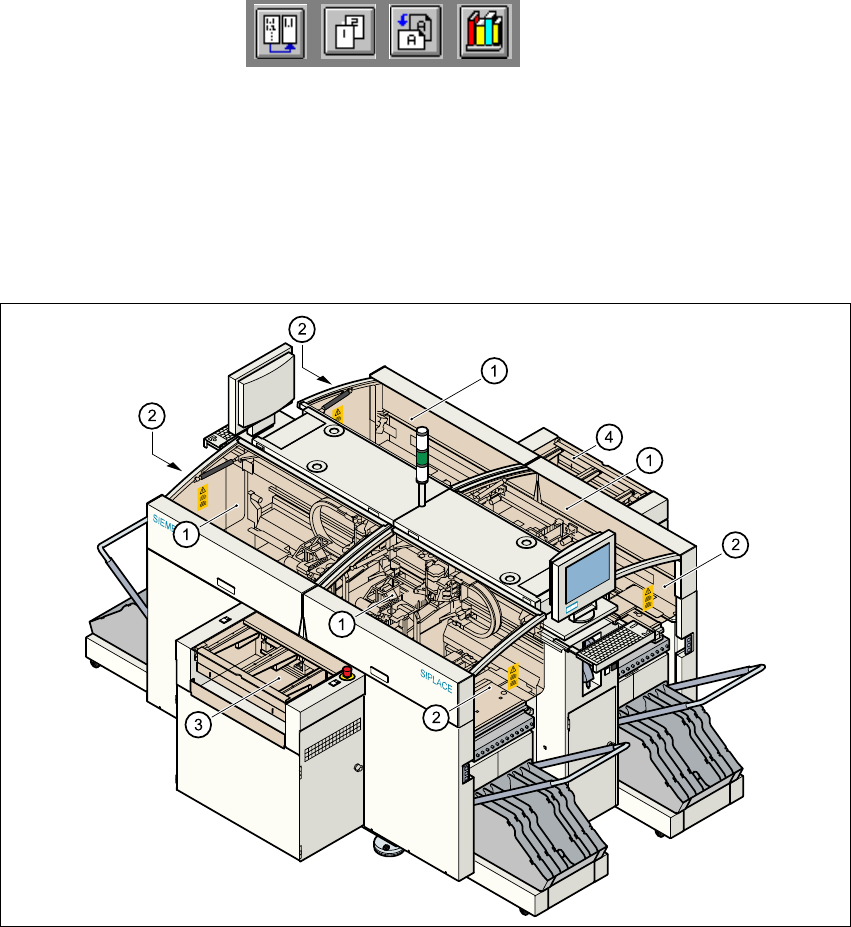
Fig. 2.2 - 1 Protective covers
2
The travelling range of the gantries is covered by four protective covers which can be folded up.
Side screens prevent access to the inside of the placement system from the side. The covers over
the input and output belts of the PCB conveyor and the guards on the input and output belts pre-
vent access to the PCB conveyor. 2
(1) Protective covers
(2) Safety screens
(3) Cover and guard on the input belt
(4) Cover and guard on the output belt