00191369-02.pdf - 第131页
User Manual HS-50 4 Placement Functions Software Vers ion SR.501.xx 12/99 Issue US 4.1 Setup Display 131 t I I t 4 Placement Functions 4.1 Setup Display If the clu ster has been spe cified wi th its co rrespondi ng se tu…
3 Introduction and Basic Concepts User Manual HS-50
3.3 User Interface - Views and Menus Software Version SR.501.xx 12/99 Issue US
130
t IIt
3.3.2.6 "Help" Menu
his menu gives you access to all the functions required to call the help system and general infor-
mation concerning the station computer or the software. 3
Content Ctrl+F1 3
This calls on-line help. 3
Help Alt+F1 3
Help information relating to the current view is displayed. 3
Use help 3
Information on how to use Help is displayed. 3
Info ... 3
This displays information on the currently installed software version (SC , MC, WPC, GEM ver-
sion) together with general information on the station computer. 3
NOTE
You can use the key combination CTRL+F1 to call the on-line Help function from within any view
in the user interface.
You can use the key combination Alt+F1 to call up help on the current view and the key combina-
tion Shift+F1 to access help on menu items, icons and buttons.
For a detailed description of the functions in the Help menu, refer to Chapter 9. 3
Å Click the required menu item in the "Help" menu or press the corresponding key combination.
3
User Manual HS-50 4 Placement Functions
Software Version SR.501.xx 12/99 Issue US 4.1 Setup Display
131
t IIt
4 Placement Functions
4.1 Setup Display
If the cluster has been specified with its corresponding setup, then the setup of each of the
4 locations can be displayed in this view.
4
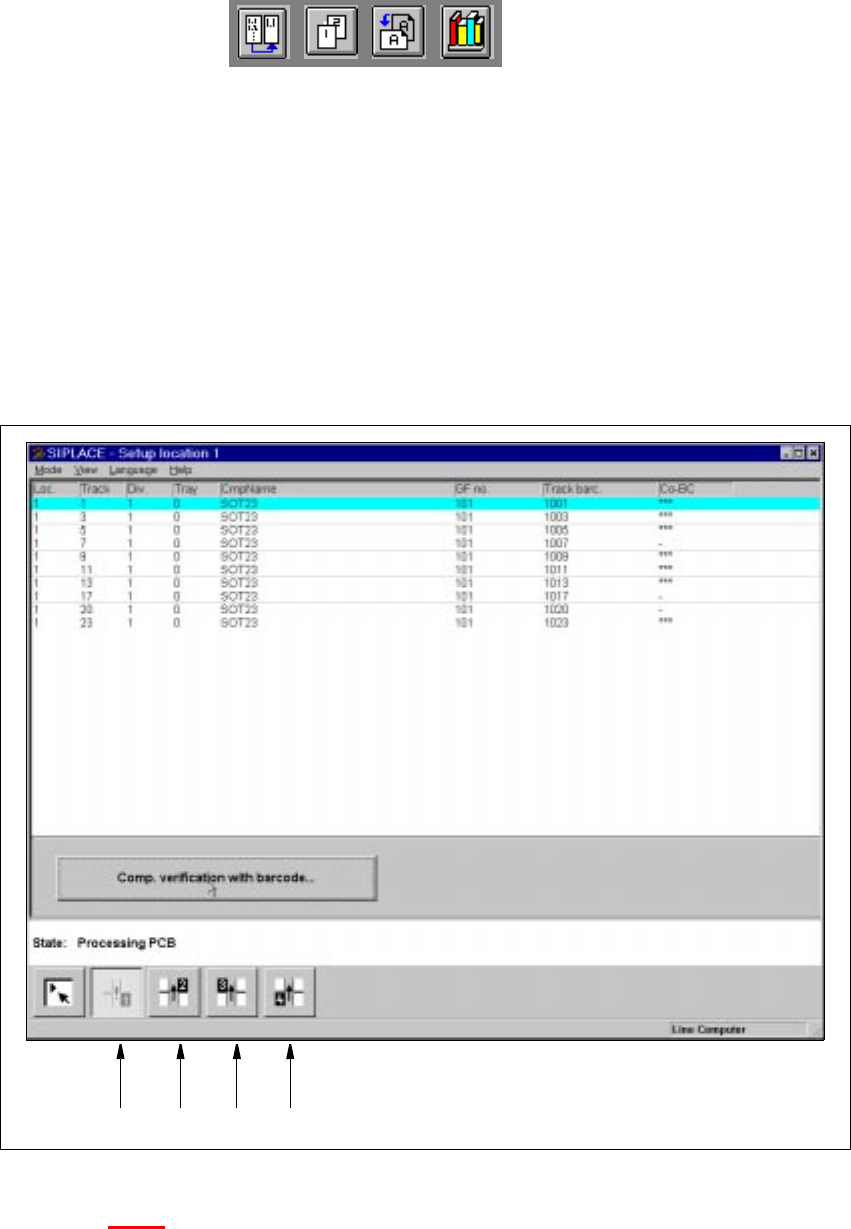
Fig. 4.1 - 1 "Setup location 1" view
Key to Fig. 4.1 - 1
(1) Display the setup for location 1
(2) Display the setup for location 2
(3) Display the setup for location 3
(4) Display the setup for location 4
1234
4 Placement Functions User Manual HS-50
4.1 Setup Display Software Version SR.501.xx 12/99 Issue US
132
t IIt
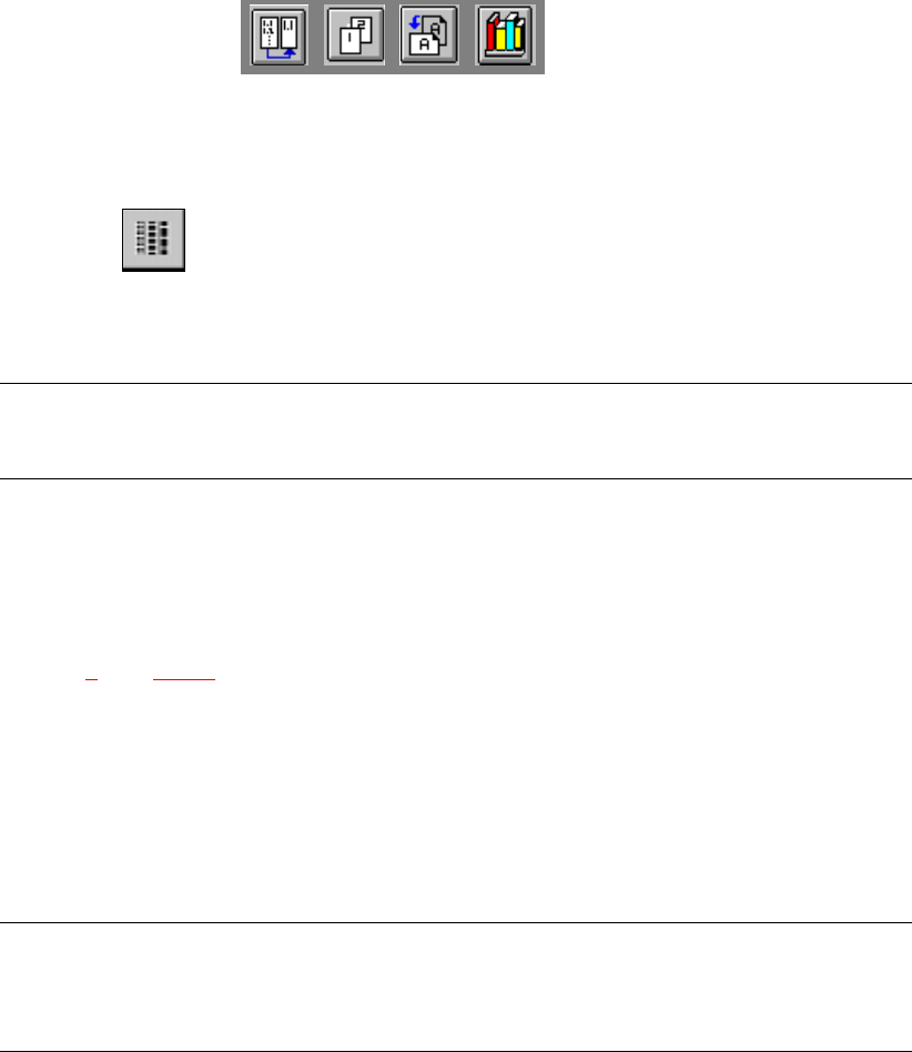
4.1.1 "Setup location x" View
4
Å Click on the icon in the toolbar in the Main view.
The user interface switches to the "Setup location x" view.
The setup data for the current location is presented in the display area in tabular form.
NOTE
The view is the same for each location. 4
4.1.1.1 Meaning of the Entries in the Setup Table
– Loc.
The number of the location whose setup is to be displayed is entered in this column. (See
Chapter 3
, Fig. 3.1 - 2 for the position of the locations)
– Track
The number of the track on which the corresponding feeder is located is entered here.
– Div.
The number of the feeder division from which the component in the corresponding feeder is to
be picked is entered in this column.
NOTE
The number for a tray division can also be entered here for other types of machines in the
SIPLACE series. 4
– Tray
This column is irrelevant when setting up the locations of a SIPLACE HS-50.
(Only valid for automatic machines with wafflepack changers).
– CmpName
The name of the corresponding component is entered in this column.
– GF no.
The number of the package form for the corresponding component is entered here.
– Track barc.
The track barcode assigned to the corresponding track is entered in this column.
– CO-BC
This column shows whether or not a component barcode has been specified for the corre-
sponding component in the setup using the "***" or "-" symbol.