00191369-02.pdf - 第308页
6 Vision functions User M anual HS-50 6.7 Guidelines for Desc ribing Package Forms Software Version SR .501.xx 12 /99 Issue U S 308 t I I t If the comp onent c annot b e center ed correc tly , additio nal me asuring meth…
User Manual HS-50 6 Vision functions
Software Version SR.501.xx 12/99 Issue US 6.7 Guidelines for Describing Package Forms
307
t IIt
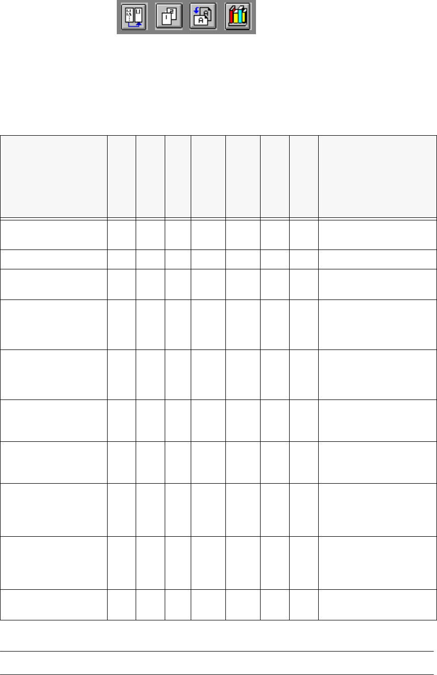
6.7.3 Shapes and possible measuring methods for rough (G) and fine centering (F)
6
6
If one or more of the results are outside the tolerance, the component will not be placed. 6
Design
SIZE
ROW
CORNER
Lead : combined
analysis windows
Lead: separate
analysis windows
GRID
BALL
Result of the
last measuring step
PDC without lead G/F
∆X, ∆Y, (∆φ), Component
length, width, (quality)
PDC rounded image G/F F Angular tolerance
Small FDCs, e.g.
2 leads
G/F F
∆X, ∆Y, (∆φ), Component
length, width, (quality)
FDC, regular with short
rows of PINs
GF
four-
sided
F
Not
four-
sided
F
Max. deviation from the
spacing: ∆X, ∆Y, ∆φ,
(quality)
FDC, regular with long
rows of PINs
GF
four-
sided
F
Not
four-
sided
F
Max. deviation from the
spacing: ∆X, ∆Y, (∆φ),
quality
FDC irregular with
short rows of PINs
G(G)F F
∆X, ∆Y, number of PINs
(quality), max. deviation
from the spacing
FDC, irregular with
long rows of PINs
G(G)F F
∆X, ∆Y, number of PINs
(quality), max. deviation
from the spacing
FDC, irregular with one
row of PINs, several
PIN models or spac-
ings
GG F
∆X, ∆Y, (∆φ), standardized
lead deviation (quality)
Number of PINs, second-
ary offset
FDCs with circular seg-
ment PIN arrange-
ments
(G) G F
∆X, ∆Y, (∆φ), standardized
lead deviation (quality)
Number of PINs, second-
ary offset
BGA, flip-chip G G F
∆X, ∆Y, (∆φ), spacing,
angle, quality)
Tab. 6.7.1 Component measuring methods

6 Vision functions User Manual HS-50
6.7 Guidelines for Describing Package Forms Software Version SR.501.xx 12/99 Issue US
308
t IIt
If the component cannot be centered correctly, additional measuring methods may be omitted.
You should, however, carry out all the rough centering steps since these reduce the size of the
measuring window. 6
– In the ’Test component’ menu, the components are optically centered in the individual measur-
ing steps, via the ’Check component’ function, but the results are not output.
– In the ’Test component’ menu, the components are optically centered in the individual measur-
ing steps, via the ’Measure component’ function, but the results are not output.
– If the components are larger than 32 mm x 32 mm, a multiple measurement will be carried out
automatically in the vision system.
User Manual HS-50 6 Vision functions
Software Version SR.501.xx 12/99 Issue US 6.7 Guidelines for Describing Package Forms
309
t IIt
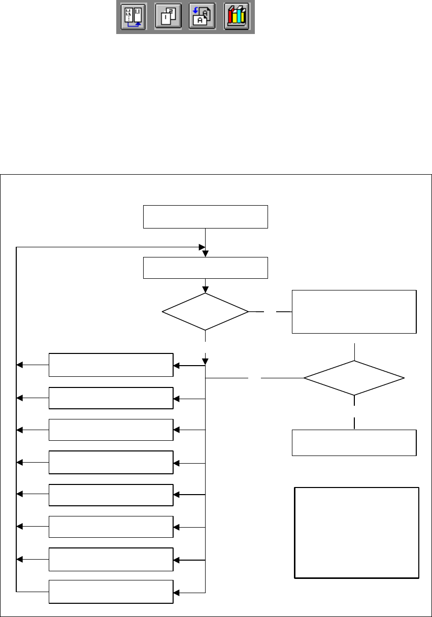
6.7.4 Test Package Form - Visual Representation /
Programming Measurement Types
In the ’Test component’ menu, a component is picked up and then moved to the camera and
mapped in its 0° position. The component is displayed with respect to its placement angle at the
revolver head. 6
6
Fig. 6.7 - 5 Order in which package forms are programmed at the station
6
No
No
Yes
Error
1. Handling error: pick-up angle,
nozzle type, CO on nozzle etc.
2. Display component
3. Modify lighting
4. Modify measuring modes
and measuring parameters
5. Modify component dimension
6. Modify pin/ball contrast
7. Modify pin/ball
dimension
8. Program contrast
(program table)
Important note:
The manipulation of
components at the station must
remain the exception, rather
than the rule.
In general, only a few
components have to
be changed.
Assemble component
several times
Repeat measurement
and check the results
Measure component
Check component, press
Return for next meas. step
Are the results
constant?
Yes