00191369-02.pdf - 第24页
1 Introduction User Manual HS-50 1.5 Description of the machine Software Version SR.501.xx 12 /99 Issue US 24 t I I t 1 The concep t behin d the au tomati c placem ent sy stem 1 – wit h its station ary feede r mod ules, …
User Manual HS-50 1 Introduction
Software Version SR.501.xx 12/99 Issue US 1.5 Description of the machine
23
t IIt
1.5 Description of the machine
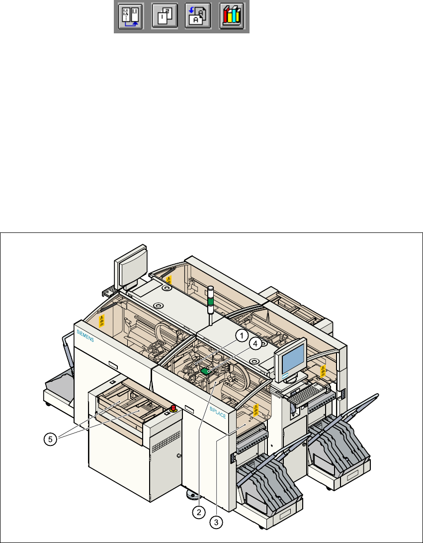
1.5.1 Functional description
The automatic placement system is a high-performance placement system with four gantry axis
systems. A PCB vision system and a star-shaped 12-segment revolver head are mounted on each
gantry. Revolver placement heads equipped with a component vision system pick up the compo-
nents from stationary feeder modules and insert them into the PCB clamped in the PCB con-
veyor. 1
1
Fig. 1.5 - 1 Functional description of the placement system
(1)12-segment revolver head/DLM1 with component vision camera
(2)Gantry axis system with PCB vision camera
(3)Stationary component feeder
(4)Clamped printed circuit board (PCB)
(5)PCB conveyor (dual conveyor option)
1

1 Introduction User Manual HS-50
1.5 Description of the machine Software Version SR.501.xx 12/99 Issue US
24
t IIt
1
The concept behind the automatic placement system 1
– with its stationary feeder modules,
– PCBs that do not move during placement
– and positionable placement heads
has a number of significant benefits: 1
– For example, the flexible 12-segment revolver heads combined with automatic nozzle chang-
ers enable the nozzle configuration to be changed temporarily and automatically adapted to
receive different component sizes. You can also optimize the traversing paths and the place-
ment sequence.
– With stationary feeder modules, even the tiniest components are picked up reliably.
– The components cannot slip on the PCB during placement (as is often the case with moving
PCBs) since the PCB does not move.
– Sophisticated optical centering systems (vision systems) for components and PCBs also en-
sure high component positioning accuracy.
– Components can be topped up and tapes can be spliced without stopping the machine.
– Prepared component tables enable the placement system to be retooled without long stop-
pages.
1.5.2 Technical data - machine overview
Range of components From 0402 to PLCC44, SO32, DRAM
Maximum placement speed of the12-segment
revolver head/DLM1
50,000 components/hour
Cycle time at the revolver head 125 ms, regardless of the type of component
Accuracy
± 90 µm at 4 sigma
± 135 µm at 6 sigma
PCB format
50 x 50 mm to 368 x 460 mm
2" x 2" to 14.5" x 18"
Feeding capacity Up to 96 tracks, each with 8 mm tapes
Feeder modules Tapes, bulk-cases
Operating system Microsoft Windows NT / RMOS
Combination options Inline or stand-alone
Space required 7.5 m² / module

User Manual HS-50 1 Introduction
Software Version SR.501.xx 12/99 Issue US 1.6 The line concept
25
t IIt
1.6 The line concept
1.6.1 Overview
The placement system can be linked to input and output stations, screen printing systems, sol-
dering ovens and other automatic placement systems from the SIPLACE range (S-20, F4, F5
and the SIPLACE G glue application station). All SIPLACE modules are supplied with the neces-
sary data by the UNIX line computer. The placement system can also be linked to a higher level
data processing system through the use of suitable interfaces.
1.6.2 Technical data - line concept
* SIPLACE HS-50, SIPLACE 80 S-20 or SIPLACE 80 F4 with 12-segment revolver head
** SIPLACE 80 F4 / F5
1
System SIPLACE placement lines
Module
SIPLACE HS-50 / SIPLACE 80 S-20/
SIPLACE 80 F4 / SIPLACE 80 F5
Peripherals
Input/output stations
Screen printers
Soldering ovens
Inspection stations, etc.
Range of components From 0402 * to 55 mm x 55 mm **
PCB conveyor Automatic width adjustment
PCB format 50 mm x 50 mm to 368 mm x 460 mm
Placement speed
Depends on how the modules are connected to one
another
Space required
4 m² / SIPLACE 80 modules
7.5 m² / SIPLACE HS-50 modules