00191369-02.pdf - 第190页
6 Vision functions User M anual HS-50 6.2 PCB vision system Software Version SR.501.xx 12/99 Is sue US 190 t I I t Measure ment takes pl ace in two stages: 6 – 2-D patter n search (2-dime nsio nal proces s) in th e coars…

User Manual HS-50 6 Vision functions
Software Version SR.501.xx 12/99 Issue US 6.2 PCB vision system
189
t IIt
– trigger and flash signals (10-pin ribbon cable connector)
and status display LEDs for 6
– the CPU (CFG)
– the vision processor (ACA)
– the camera input (BCA)
– the screen display (DISP)
6.2.2 Technical Data
Camera model: SONY XC75 6
Number of pixels: Camera 768 (H) x 494 (V), Image 640 (H) x 484 (V) 6
Field of view: 5.7 mm x 5.7 mm 6
Illumination method: Incident light method (activated during measurement) 6
Image processing: Correlation principle, gray scale system 6
Processor cycle time: < 200 msec 6
Screen: RGB monitor (VGA mode) 640 x 484 pixels in the station computer6
Fiducials: Library memory for up to 255 fiducial definitions 6
6.2.3 Description of Functions
Before placement the location, skew and shear of the board is determined by the PCB vision sys-
tem using the position of the fiducials. Deviations from the setpoint values are then included in the
calculation of the placement positions of the components as corrections. 6
A board must have at least 2 fiducials if the system is to be able to detect deviations in the board
position and the skew of the board. The presence of 3 fiducials will furnish additional information
concerning shear or stretching of the board or of the board layout. 6
6.2.4 Sequence of Functions
Before a fiducial can be used for board recognition it must first be ’taught’ to the machine. In other
words, the fiducial structure parameters must have been saved in the PCB vision system for that
pattern. 6
The fiducial structure can be taught using the PCB vision camera mounted on the gantry and the
vision program. The vision analysis unit determines the significant fiducial structure parameters
using digital image processing methods. 6
6 Vision functions User Manual HS-50
6.2 PCB vision system Software Version SR.501.xx 12/99 Issue US
190
t IIt
Measurement takes place in two stages: 6
– 2-D pattern search (2-dimensional process) in the coarse grid and provisional determina-
tion of the fiducial coordinates
– 1-D pattern search (1-dimensional process) for a precise determination of the position of
the fiducials.
With the 2-D pattern search process the template window is divided into moxel areas. Moxels
(mosaic pixels) are pixel fields containing for example 16 x 16, 8 x 8 pixels and so on. The lower
the pixel count per moxel the higher the resolution and the lower the search speed. 6
6
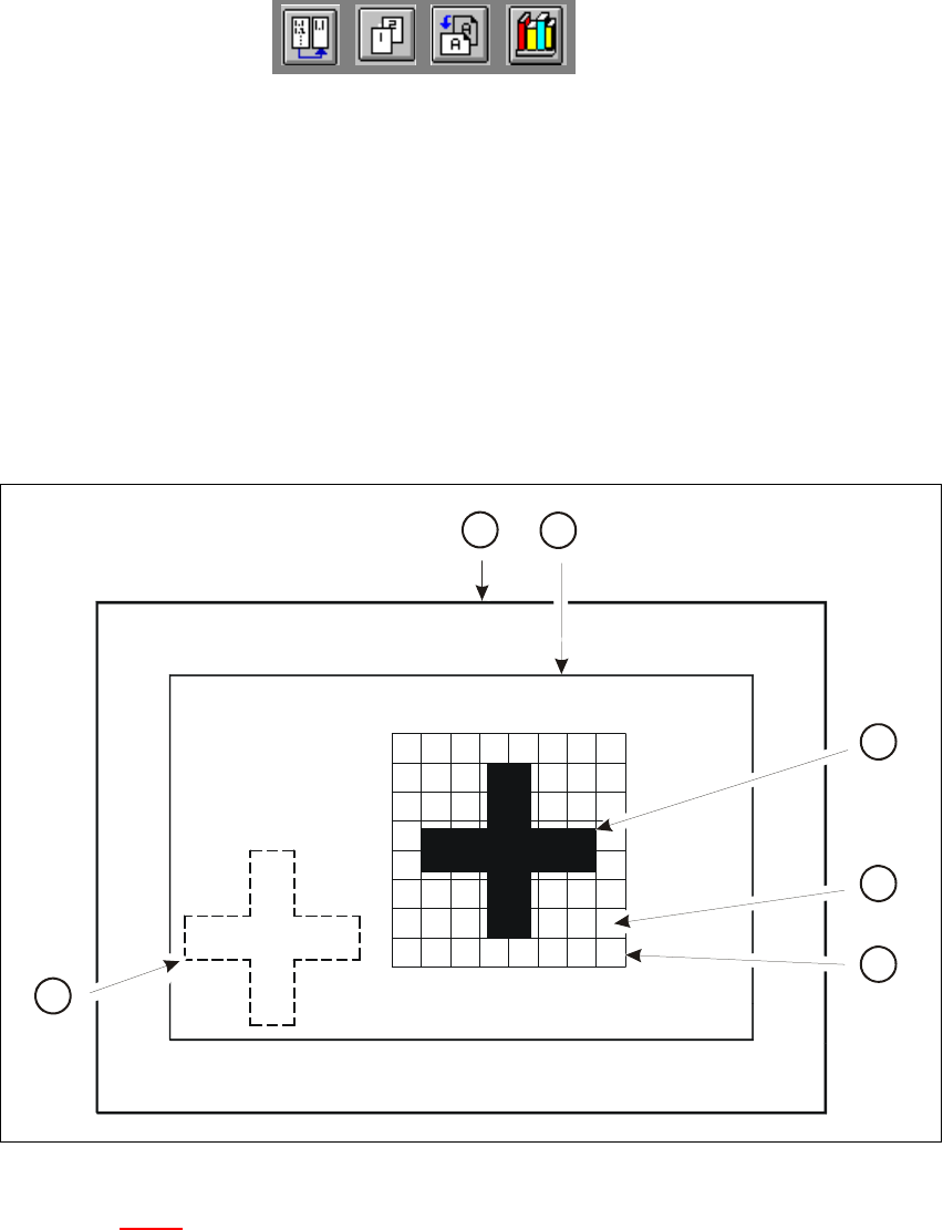
Fig. 6.2 - 1 Explanation of camera field of view, search area and template window
Key to Fig. 6.2 - 1
(1) Camera field of view
(2) Search area ≤ camera field of view (the fiducial is searched for in this area)
(3) Reference fiducial
(4) Moxel = pixel field, eg 16 x 16 pixels
(5) Template window (it contains the reference fiducial)
(6) Fiducial which is to be searched for
4
2
5
6
3
1
User Manual HS-50 6 Vision functions
Software Version SR.501.xx 12/99 Issue US 6.2 PCB vision system
191
t IIt
The template window is moved over the search area in moxel steps. The gray scale values of each
moxel of the reference fiducial are calculated at this time. This reduced data structure will contain
enough information on the coarse structure and position of the reference fiducial. 6
NOTE 6
The search window should be as small as possible in order to keep the speed of searching high.
On the other hand the window should be large enough to allow the fiducial to be identified with-
out ambiguity.
The 1-D pattern search procedure is used for precisely determining the pattern and position of the
fiducial. The fiducial image is broken up into rows and columns and the gray scale values in each
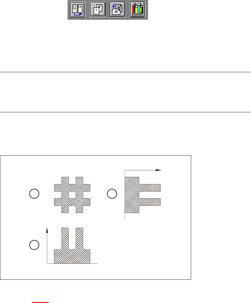
row and column added up. The next diagram illustrates this process using a double cross. 6
6
Fig. 6.2 - 2 Row and column profile of a double cross
Key to Fig. 6.2 - 2
(1) Fiducial
(2) Sum of the grey scale values in one column: column profile
(3) Sum of the grey scale values in one row: row profile
6
– The position of the fiducial is precisely determined from the horizontal and vertical profiles.
After teaching, the fiducial structure parameters obtained are saved to the line computer.
– The saved pattern is now tested. The gantry moves the PCB camera over the board to all 4
corners of the search area (worst case). During this test the vision system must re-identify the
fiducial four times.
– Finally, the coordinates of each individual fiducial (at least two) are manually added to the NU
1
2
3