00191369-02.pdf - 第185页
User Manual HS-50 6 Vision functions Software Version S R.501.xx 12/99 Issue US 6.1 The vision systems on the placement system 185 t I I t 6.1.3 Vision ana lysi s unit s The two vis ion anal ysis u nits (see i tems 1 and…
6 Vision functions User Manual HS-50
6.1 The vision systems on the placement system Software Version SR.501.xx 12/99 Issue US
184
t IIt
6.1.2 PCB camera systems
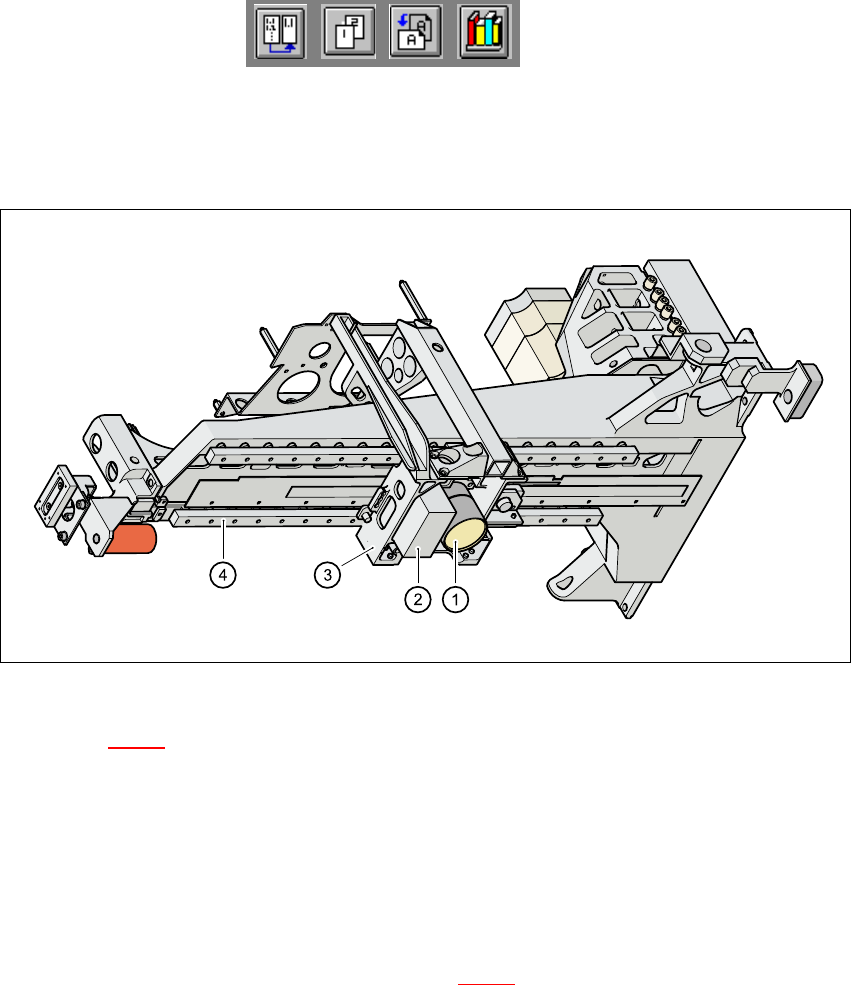
Fig. 6.1 - 3 PCB camera system, basic gantry - bottom view
Key to Fig. 6.1 - 3
(1) PCB camera - lens and illumination
(2) Camera amplifier
(3) Head mount
(4) Gantry
6
The PCB camera system (see items 1 and 2 in Fig. 6.1 - 3
) essentially consists of the following
components: 6
– Lens system
– CCD chip
– CCD camera amplifier
– An illumination plane for illuminating PCB fiducials and ink spots
The PCB camera system is fixed to the revolver head mount on the underside of the gantry. As
standard, it can center PCBs from 50 mm x 50 mm up to 368 mm x 460 mm (2" x 2" to 14.5" x 18")
in size, with the thickness ranging from 0.5 mm to 4.5 mm. 6
User Manual HS-50 6 Vision functions
Software Version SR.501.xx 12/99 Issue US 6.1 The vision systems on the placement system
185
t IIt
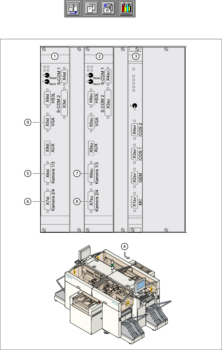
6.1.3 Vision analysis units
The two vision analysis units (see items 1 and 2 in Fig. 6.1 - 4) are plugged into the placement
system’s control unit. 6
They process and analyze electrical signals from the component and PCB camera systems. Cor-
rection values are calculated from any deviations from setpoint. These values are then used for
recalculating the placement positions and angle of rotation for placement. 6
The vision analysis units also perform a component identification process. The precise component
pick-up position, which is particularly important for small components, is also determined in the
vision analysis units. 6