00191369-02.pdf - 第338页
7 What should you do ... User Manual HS -50 7.8 How to avo id track errors S oftware Version SR.501.xx 12/99 Issue US 338 t I I t 7.8.2 ... on the 8 mm S t ape feeder module Å NEV ER open th e cover fl ap without fi rst …
User Manual HS-50 7 What should you do ...
Software Version SR.501.xx 12/99 Issue US 7.8 How to avoid track errors
337
t IIt
7.8 How to avoid track errors
7.8.1 General information
Å Make sure that the areas around the feeder modules are clean and that there are no loose
components in the feeder area or under the feeder modules.
Å Ensure that the supporting surfaces of the feeder modules, and particularly the magnetic rails
of the component tables, are clean and level.
Å Refill promptly with components.
Å Splice the tapes promptly. This generally means that you are to prepare the splicing material
when there is still approximately 1.5 m of tape on the reel.
Å Handle the feeder modules carefully when you insert them into or remove them from the com-
ponent table as these are high-precision devices.
Å When you insert the feeder modules, make sure that you do not accidentally press one of the
program keys. If you do, you could change the advance from 4 mm to 2 mm on
8 mm S feeder modules, for example.
Å Close the flaps of the feeder modules because they can be easily damaged when open.
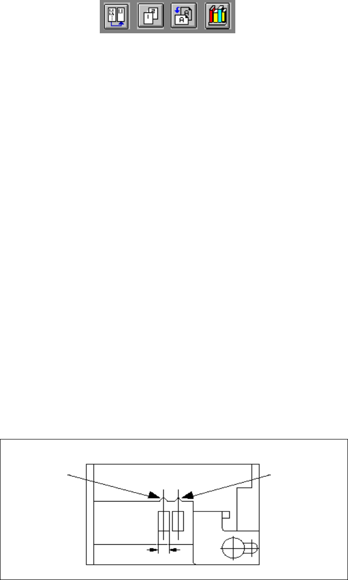
Å For 8 mm S feeder modules, make sure that the components are picked up from the correct
position, depending on their sizes (see the following example).
Example for 8mm S feeder modules 7
7
Å Check to see if all the plugs of the feeder modules are plugged in to the correct sockets.
Pick-up position
Pick-up position
> 3 mm
for components
< 3 mm
for components
Width

7 What should you do ... User Manual HS-50
7.8 How to avoid track errors Software Version SR.501.xx 12/99 Issue US
338
t IIt
7.8.2 ... on the 8 mm S tape feeder module
Å NEVER open the cover flap without first releasing the tension of the cover foil remover.
Å Set the pick-up position and the spacing of the tape according to the short instructions en-
closed with each tape feeder module.
Å Insert the tape material over the spring into the tape feeder module.
7.8.3 ... on the tape container
Å Insert the spacers correctly (see Fig. 7.5 - 2).
Å Use insertable shafts for large tape reels.
User Manual HS-50 7 What should you do ...
Software Version SR.501.xx 12/99 Issue US 7.8 How to avoid track errors
339
t IIt
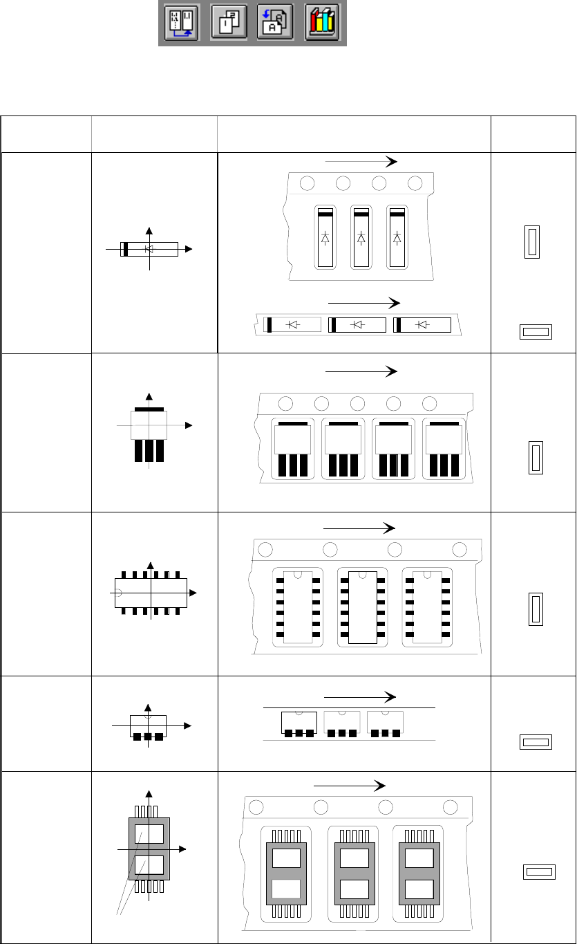
7.8.4 Component coordinate system and pick-up angle
7
Fig. 7.8 - 1 Position of the component and its pick-up angle
0°
90°
90°
SO-IC
DIL-IC
0°
SOT 194
90°
90°
SOT 23
Y
X
Vibratory feeder:
Special
Component
Chip
component
with
polarity
0402
2220
Component
type
Coordinate system Position in the feeder
Pick-up angle
nozzle angle
Tape
Tape
Vibratory feeder:
Tape
Tape
Y
X
Y
X
Holes
Y
X
Y
X
The anode must be
aligned with the
+x-coordinate