00191369-02.pdf - 第278页
6 Vision functions User M anual HS-50 6.6 Test Component Software V ersion SR.501.xx 12/99 Issue U S 278 t I I t Å Y ou can use the ar row keys to in crease or d ecrease th e bri ghtness of the rows of LEDs in the compon…
User Manual HS-50 6 Vision functions
Software Version SR.501.xx 12/99 Issue US 6.6 Test Component
277
t IIt
– Illumination parameters are
– the contrast in the image
– the X plane, flat, middle and steep illumination levels for illuminating the component
(brightness control).
– Color representation parameters (5 sections)
– 10 parameter IN values
– 10 parameter OUT values
The parameters are stored in the GF file in the line computer. Upon request the GF file will be sent
to the station computer. Finally it will be converted and transferred to the MVS controller. 6
If you modify a parameter, it will be entered in the x.SST file. The x.SST file will be converted and
loaded into the MVS controller. 6
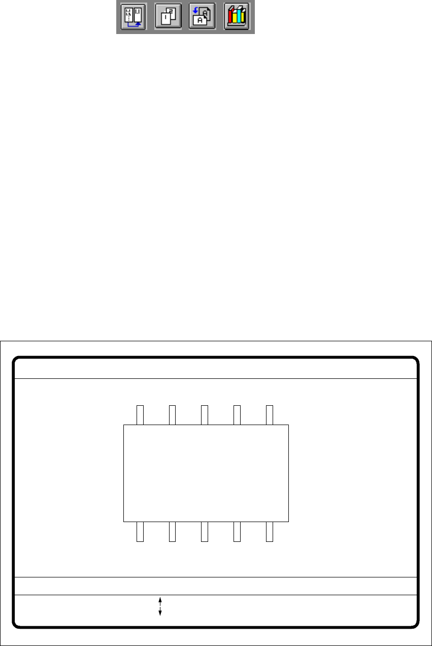
6.6.4.8 Illumination Option
When this option is selected the video image for checking and setting illumination will appear. 6
6
Fig. 6.6 - 26 Test component menu, Illumination video image
6
GF No. = 5Illumination
RET: Test component
Illuminat. = flat/middle/steep Field step =
Blank: step width
Tab: Illumination
Brightness = 0 ... 255
: Brightness up
: Brightness down
6 Vision functions User Manual HS-50
6.6 Test Component Software Version SR.501.xx 12/99 Issue US
278
t IIt
Å You can use the arrow keys to increase or decrease the brightness of the rows of LEDs in the
component camera system which illuminate the component. The brightness can be set within
a range of 256 steps with 255 being the maximum value.
Å Use the spacebar to toggle the step size for changing the brightness from 1 to 10 µm and back.
Å Use the tab key to move between the three illumination levels: steep (top row of LEDs), me-
dium (second row of LEDs) and flat (third row of LEDs) camera lighting.
Å Press the Return key to execute the individual measurement steps which are included in the
measurement conditions.
Å With Esc you can quit the option. You will then be returned to the Test component menu.
6
NOTE 6
Section 6.7.6 from page 311 contains instructions for selecting the illumination parameters.
User Manual HS-50 6 Vision functions
Software Version SR.501.xx 12/99 Issue US 6.6 Test Component
279
t IIt
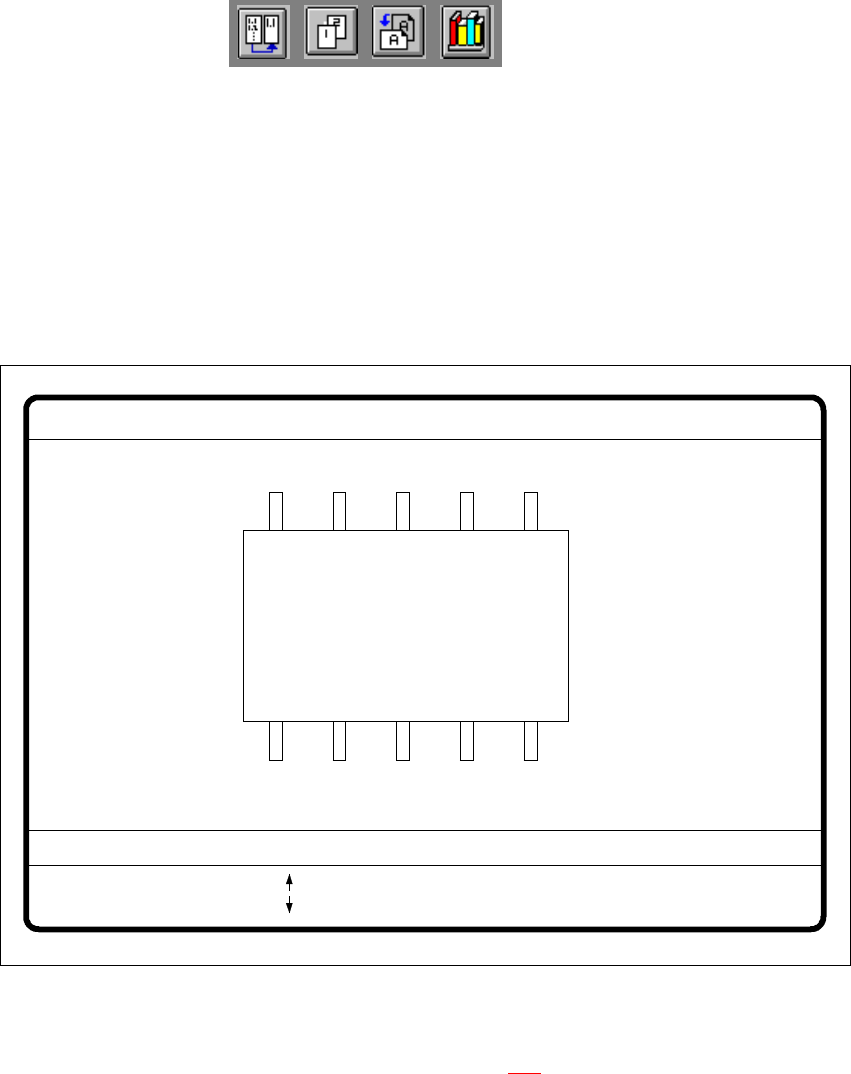
6.6.4.9 Package Dimension Option
There is potential for the occurrence of an effect called image reduction mainly with cylindrical
components, with PLCCs, BGAs and µBGAs. The reduction is caused by the round features of
the components that deflect incident light away from the camera sensor. Typically, the round
edges then become invisible to the camera. To remedy this problem, use the Package Dimension
option to change the optical package width and length to accommodate for the loss. 6
6
Fig. 6.6 - 27 Test component menu, Package dimension video image
Å With the arrow keys you can change the length and width of the component. The current geo-
metric data will be displayed (see description on page 276
).
Å Use the spacebar to select different sides of the component.
Å With the Return key you can trigger the individual measurement steps which are specified in
the measurement conditions.
Å Press Esc to quit the option.
GF No. = 5
: larger
: smaller
RET: Test component
Blank: Pack. side
Pack. side = opt. l.[mm] = ... opt. w.[mm] = ...
Package dimension