00191369-02.pdf - 第264页
6 Vision functions User M anual HS-50 6.6 Test Component Software V ersion SR.501.xx 12/99 Issue U S 264 t I I t 6 Fig. 6.6 - 21 T est component menu, Measure compon ent video image Optical sur veying of conv entional co…
User Manual HS-50 6 Vision functions
Software Version SR.501.xx 12/99 Issue US 6.6 Test Component
263
t IIt
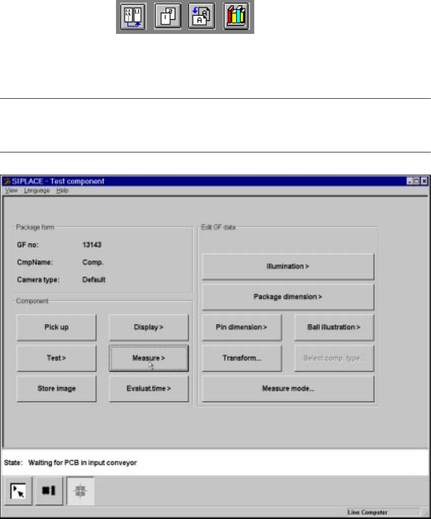
6.6.4.4 Measure Component Option
NOTE 6
This option can only be activated if you have already loaded a package form number and a com-
ponent has been picked up.
6
Fig. 6.6 - 20 Test component menu, Measure component option
When this option is activated the following actions are started: 6
– The video image appears on the screen.
– The measurement command is given, using the predefined parameters.
– The MVS performs each component-specific measurement step in turn.
– The measurement values are displayed in the video image.
6 Vision functions User Manual HS-50
6.6 Test Component Software Version SR.501.xx 12/99 Issue US
264
t IIt
6
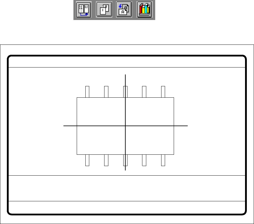
Fig. 6.6 - 21 Test component menu, Measure component video image
Optical surveying of conventional components with lead connections 6
The crosshairs indicate the component’s center. The component outlines are emphasized in color. 6
The measured values represent the geometric component parameters such as 6
– Lead skew
The value for lead skew will be indicated if you have selected the lead or ball measurement
mode.
–Pitch
The value for pitch will be indicated if the corner measurement mode is active as the last mea-
surement step.
– Number of leads
– X / Y offset
– Orthogonality
– Dimensions of the component
–Skew and
– Factor for the quality of measurement.
Measure component GF No. = 5
X offset = ... Y offset = ... Phi = ...
Orthogon = ...
No. of pins = ...
Quality fact. = ...
Length[mm] = ...
Width[mm] = ...
Spacing[mm] =
RET: Measure component
P.dev.[mm] =
User Manual HS-50 6 Vision functions
Software Version SR.501.xx 12/99 Issue US 6.6 Test Component
265
t IIt
Use Esc to quit this option. The video image disappears and the Test component menu is dis-
played once more on the screen. 6
Color overlays of the individual measurement steps during step mode 6
1. Size mode 6
See Section 6.6.4.14
on page 289 for a definition of the measuring methods. 6
You can recognize this measurement method by rotating windows around the component edges 6
Procedure: 6
(1) Inside the search window, profiles are created in the X and Y directions. With the aid of the
gradients thus formed and a geometric filter, the approximate position of the component is
determined.
(2) Windows rotate around the component’s edges. The profile and gradients are determined for
each window. The sum of the gradients is an indication of the agreement of the window angle
with the position of the component.
If the sum of the gradients reaches a maximum, the angular position of the component has
been determined.
(3) Under the angle determined in step (2) the first step (1) is repeated. Now it will be possible
to determine the position of the component in the X and Y-directions more accurately.
Rectangles:
green: X and Y- pick-up tolerances 6
orange: component dimensions and tolerances supplied by the station 6
blue: search area for position recognition 6
6
Comments 6
1. The position of the component as determined must be within the green rectangle
otherwise the component will not be placed. 6
Applies to all measurement steps! 6
2. The component must be located within the orange window. Otherwise the measurement
results will not be dependable. 6
6
3. The search areas should have the same alignment as the component and also be larger
than the component. 6