00191369-02.pdf - 第271页
User Manual HS-50 6 Vision functions Software Version S R.501.xx 12/99 Issue US 6.6 Test Comp onent 271 t I I t Poi nt s marked with red p lus s igns (+) : 6 outside the c ircle: Contras t < 0, ball is dar ker than th…

6 Vision functions User Manual HS-50
6.6 Test Component Software Version SR.501.xx 12/99 Issue US
270
t IIt
The number of balls to be measured and the pattern tolerances define the size of the search win-
dow. The rough position and the skew of the component are determined for each corner of the
component via a search window. This measurement method can be identified by 6
– the synthetic model being shown in pixel resolution at the lefthand edge of the video image,
and
– the 4 windows at the corners of the component.
Procedure: 6
– The algorithm defines 4 dark blue corner windows on the basis of the pattern tolerances and
the balls defined in the package form file. The default search value is 5 balls.
– A detection algorithm runs with the aim of detecting all balls corresponding to this type. Those
found will be marked with light blue crosses.
– The balls defined in the package form file are determined by the search algorithm. The balls
found are marked with a white outline. If defined balls are not found an error message will ap-
pear on the screen.
– From these data the rough position and the skew of the component are determined. The mea-
sured position of the component is marked with white crosshairs.
Rectangle: 6
dark blue: 4 search windows, depending on the pattern tolerances and
the number of balls 6
Cross: 6
white: Ball model candidates found 6
Overlays: 6
white: Balls found which are defined in the package form file 6
Crosshairs: 6
white: Results of position recognition -> X and Y-angles 6
Star: 6
white: Center of the component -> Position 6
Synthetic model representation at the lefthand edge of the video image: 6
Image: Model in pixel resolution 6

User Manual HS-50 6 Vision functions
Software Version SR.501.xx 12/99 Issue US 6.6 Test Component
271
t IIt
Points marked with red plus signs (+): 6
outside the circle:
Contrast < 0, ball is darker than the background 6
within the circle:
Contrast > 0, ball is lighter than the background 6
Points marked with yellow minus signs (-): 6
The difference between the plus and minus signs represents
the radial tolerance. 6
2. Ball mode 6
See Section 6.6.4.14
on page 289 for a definition of the measuring methods. 6
The method works with high precision and is thus suitable for precisely determining the position
of all defined balls. As a higher precision search, ball mode will follow grid mode. 6
This measurement method can be identified 6
– by the synthetic model being shown in pixel resolution at the lefthand edge of the video image,
– by there being a window around every ball (separate window) or
Procedure: 6
All of the balls defined in the package form file are surveyed. Geometric criteria are used here in
the selection of the window mode: 6
– If the balls are relatively far apart the separate window mode will be selected. The default win-
dow mode is the separate window mode.
Window: 6
dark blue: Over a single ball in each case (separate window) 6
Over a row or over all balls (combined window) 6
Cross: 6
white: Measured ball candidates which are defined in the package form file. 6
Crosshairs: 6
white: Results of position recognition -> X and Y-angles 6
Star: 6
white: Position of the component 6
6 Vision functions User Manual HS-50
6.6 Test Component Software Version SR.501.xx 12/99 Issue US
272
t IIt
Synthetic ball model representation 6
in pixel resolution on the lefthand edge of the video image 6
A description will be found in the Grid mode section. 6
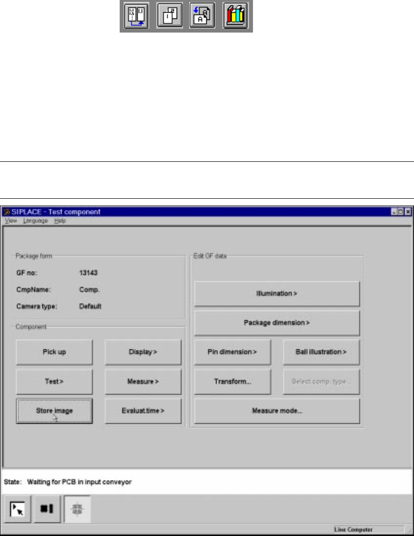
6.6.4.5 Store image Option
NOTE 6
You cannot click on this option until a package form number has been loaded.
Fig. 6.6 - 22 Test component menu, Store image option
This menu is used to store the generated video image as a file on the hard disk of the machine
controller. The file name and path are preset to: 6
D:\TMP\MVSBILD.MVS 6
For further analysis at Siemens AG, copy the file from the hard disk of the MVS controller onto a
diskette and send it to the PL EA Service Department. 6