00191369-02.pdf - 第25页
User Manual HS-50 1 Introduction Software Version S R.501.xx 12/99 Issue US 1.6 The line concept 25 t I I t 1.6 The line concept 1.6. 1 Over view The place ment sys tem ca n be li nked to i nput an d output stations , sc…

1 Introduction User Manual HS-50
1.5 Description of the machine Software Version SR.501.xx 12/99 Issue US
24
t IIt
1
The concept behind the automatic placement system 1
– with its stationary feeder modules,
– PCBs that do not move during placement
– and positionable placement heads
has a number of significant benefits: 1
– For example, the flexible 12-segment revolver heads combined with automatic nozzle chang-
ers enable the nozzle configuration to be changed temporarily and automatically adapted to
receive different component sizes. You can also optimize the traversing paths and the place-
ment sequence.
– With stationary feeder modules, even the tiniest components are picked up reliably.
– The components cannot slip on the PCB during placement (as is often the case with moving
PCBs) since the PCB does not move.
– Sophisticated optical centering systems (vision systems) for components and PCBs also en-
sure high component positioning accuracy.
– Components can be topped up and tapes can be spliced without stopping the machine.
– Prepared component tables enable the placement system to be retooled without long stop-
pages.
1.5.2 Technical data - machine overview
Range of components From 0402 to PLCC44, SO32, DRAM
Maximum placement speed of the12-segment
revolver head/DLM1
50,000 components/hour
Cycle time at the revolver head 125 ms, regardless of the type of component
Accuracy
± 90 µm at 4 sigma
± 135 µm at 6 sigma
PCB format
50 x 50 mm to 368 x 460 mm
2" x 2" to 14.5" x 18"
Feeding capacity Up to 96 tracks, each with 8 mm tapes
Feeder modules Tapes, bulk-cases
Operating system Microsoft Windows NT / RMOS
Combination options Inline or stand-alone
Space required 7.5 m² / module

User Manual HS-50 1 Introduction
Software Version SR.501.xx 12/99 Issue US 1.6 The line concept
25
t IIt
1.6 The line concept
1.6.1 Overview
The placement system can be linked to input and output stations, screen printing systems, sol-
dering ovens and other automatic placement systems from the SIPLACE range (S-20, F4, F5
and the SIPLACE G glue application station). All SIPLACE modules are supplied with the neces-
sary data by the UNIX line computer. The placement system can also be linked to a higher level
data processing system through the use of suitable interfaces.
1.6.2 Technical data - line concept
* SIPLACE HS-50, SIPLACE 80 S-20 or SIPLACE 80 F4 with 12-segment revolver head
** SIPLACE 80 F4 / F5
1
System SIPLACE placement lines
Module
SIPLACE HS-50 / SIPLACE 80 S-20/
SIPLACE 80 F4 / SIPLACE 80 F5
Peripherals
Input/output stations
Screen printers
Soldering ovens
Inspection stations, etc.
Range of components From 0402 * to 55 mm x 55 mm **
PCB conveyor Automatic width adjustment
PCB format 50 mm x 50 mm to 368 mm x 460 mm
Placement speed
Depends on how the modules are connected to one
another
Space required
4 m² / SIPLACE 80 modules
7.5 m² / SIPLACE HS-50 modules
1 Introduction User Manual HS-50
1.7 Connection data for the placement system Software Version SR.501.xx 12/99 Issue US
26
t IIt
1.7 Connection data for the placement system
1.7.1 Electrical and pneumatic connection points on the placement system
1
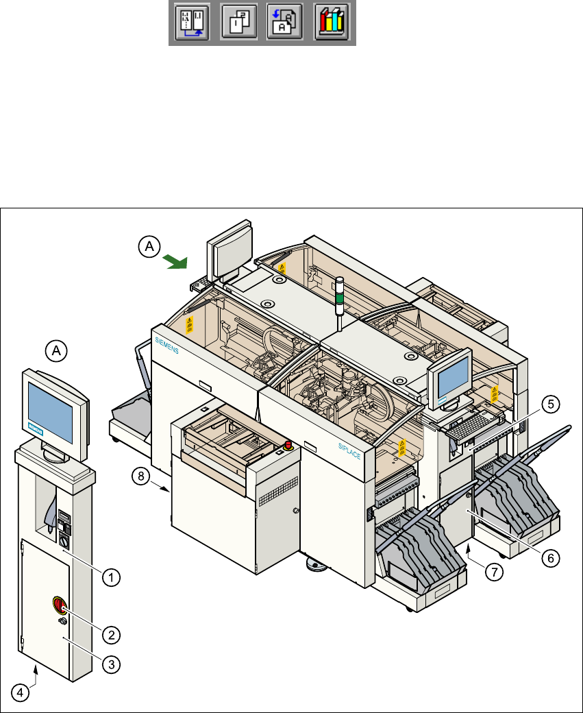
Fig. 1.7 - 1 Electrical and pneumatic connection points on the placement system
(1) Operating panel, left
(2) Main switch
(3) Safety doors to the power supply unit
(4) Hole for the power cable
(5) Operating panel, right
(6) Safety doors to the compressed air unit
(7) Hole for the compressed air line
(8) LAN connection on the station computer