00191369-02.pdf - 第300页
6 Vision functions User M anual HS-50 6.6 Test Component Software V ersion SR.501.xx 12/99 Issue U S 300 t I I t PLEAS E NOTE: Measure ment mo de Grid can b e speeded up, if m easurem ent mod e Size i s ca rried out b ef…
User Manual HS-50 6 Vision functions
Software Version SR.501.xx 12/99 Issue US 6.6 Test Component
299
t IIt
Windows 6
–
Separately for each lead
Here you define the window in the primary direction (dark blue) and secondary direction (light
blue) for measuring each standard lead for irregular components and special components.
–
Combined window
Used to define a common window for all the leads. This applies to four-sided, symmetrical
components only.
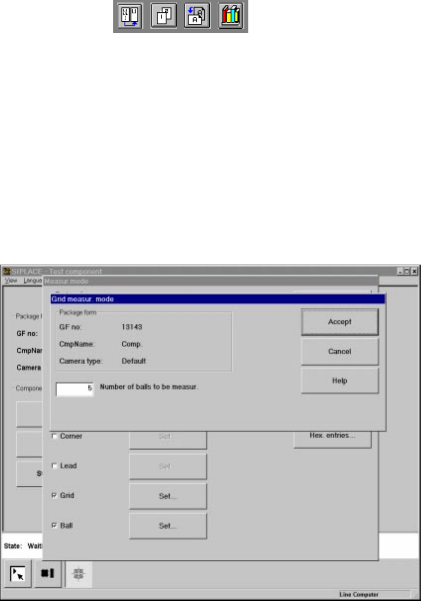
6.6.4.20 ‘Grid’ measuring mode
Click on the ‘Setting’ field in the ‘Grid’ measuring mode to call up the Grid measuring mode
menu. 6
6
Fig. 6.6 - 41 Measuring mode option, Grid measuring mode menu
In this menu, enter the number of balls to be measured at each corner: 6
– ’3’ for single measurement
– 5 for multiple measurement
6 Vision functions User Manual HS-50
6.6 Test Component Software Version SR.501.xx 12/99 Issue US
300
t IIt
PLEASE NOTE:
Measurement mode Grid can be speeded up, if measurement mode Size is carried out before-
hand. 6
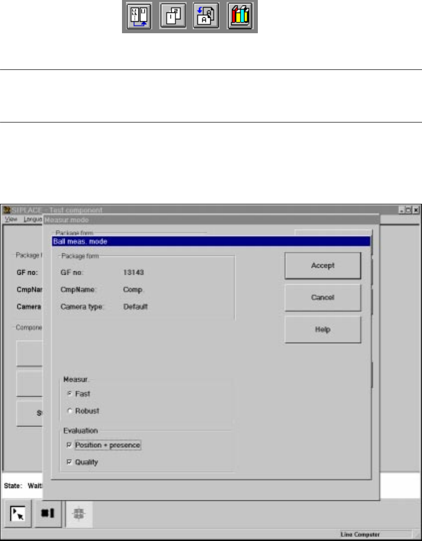
6.6.4.21 ’Ball’ measuring mode
Click on the ’Settings’ button in ’Ball’ measuring mode to call up the ’Ball measuring mode’ menu.6
6
Fig. 6.6 - 42 ’Measuring mode’ option, ’Ball meas. mode’ menu
This menu can be used to 6
– select the measuring methods listed under ’Measurement’ and
– evaluate the position and presence of balls and carry out a quality analysis.

User Manual HS-50 6 Vision functions
Software Version SR.501.xx 12/99 Issue US 6.6 Test Component
301
t IIt
Measurement 6
You can choose between the following measuring methods: 6
– the profile method for fast analysis or
– the filter method for a more robust measuring method, although this will take longer.
The ’fast’ measuring method is generally sufficient. However, for critical components we recom-
mend the ’robust’ measuring method if the quality is insufficient, for example if the quality factor is
less than 50. 6
Analysis 6
This is used to analyze the position of the balls and to determine whether they are present. It can
also be used to determine the quality of the measurement. The quality of the measurement should
generally be better than 50. 6
If you are placing BGAs, µBGAs or flip-chips with high reproducibility, i.e. if there is very little dif-
ference between the optical parameters of the components, we recommend the following settings
to guarantee fast placement: 6
– Switch off the determination of position / presence for components with large balls and spac-
ing. The position of the components has already been adequately determined using the grid
measurement of 3 balls per corner, and the ball presence analysis is unnecessary.
– Do not activate determination of the quality of the measurement unless you want to detect han-
dling or production errors.
Determination of the position is always necessary if the individual ball positions differ greatly from
the grid structure, i.e. if the individual ball positions are fairly scattered about the desired position.6