00191369-02.pdf - 第162页
5 Single Functions User Manual HS -50 5.2 Single functions, Gantry Soft ware Version S R.501.xx 12 /99 Issue US 162 t I I t 5.2.3 "V acuum test" screen Å In the current scre e n for the si ngle functions f or G…

User Manual HS-50 5 Single Functions
Software Version SR.501.xx 12/99 Issue US 5.2 Single functions, Gantry
161
t IIt
5.2.2.1 Functions
In the "Gantry functions" screen the following functions are available to test the currently selected
gantry. The required function is triggered by clicking on the corresponding button. 5
Go to set-up position 5
This function is used to check the set-up position of the gantry.
When the gantry is in the set-up position, it is possible to unload and retool the feeders.
Å Click the Go to set-up position button and press the start button as often as you are asked to.
The gantry moves (from the feeder area) into the set-up position.
Go to service position 5
This function is used to check the service position of the gantry.
When the gantry is in the service position, it is possible to carry out work on the placement head
and on other parts of the gantry.
Å Click the Go to service pos’n button and press the start button as often as you are asked to.
The gantry moves into the service position.
Go to waiting position 5
This function is used to check the waiting position of the gantry.
When the gantry is not required for placement, it moves to the waiting position.
Å Click the Go to waiting pos’n button and press the start button as often as you are asked to.
The gantry moves into the waiting position.
Go to zero pulse 5
This function is used to check the zero pulse of the gantry.
The zero pulse is the origin of the gantry to which the counting procedures of the incremental
encoder refer. For a reference run, the gantry moves to this origin.
Å Click the Go to zero pulse button and press the start button as often as you are asked to.
The gantry moves to the origin of the x and y axes.
Gantry reference run 5
This function is used to perform a reference run with the x and y axes of the active gantry. The
axes move to the origin to determine their position in the machine.
Å Click the Gantry reference run button and press the start button as often as you are asked to.
The gantry performs a reference run.
5 Single Functions User Manual HS-50
5.2 Single functions, Gantry Software Version SR.501.xx 12/99 Issue US
162
t IIt
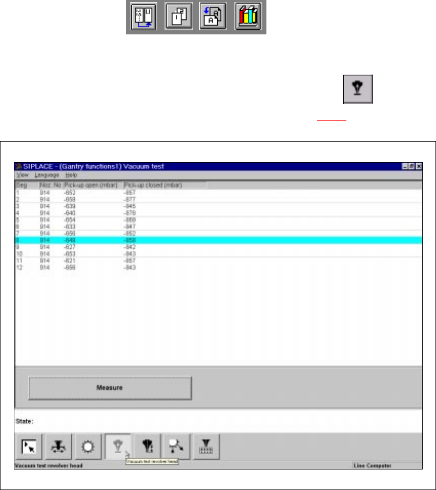
5.2.3 "Vacuum test" screen
Å In the current screen for the single functions for Gantry x, click the symbol .
The user interface is switched to the "Vacuum test" screen (see Fig. 5.2 - 3
).
5
Fig. 5.2 - 3 "Vacuum test" screen
5.2.3.1 Functions
In the "Vacuum test" screen only the "Measure" button is available. This is used to start the vac-
uum test for all nozzles.
Measure 5
This function is used to start a head reference run. This measures the vacuum values in the open
and closed pick-up positions for each of the nozzles. 5
Å Click the Measure button.
The vacuum calculation procedure is started.
The calculated vacuum values for each of the nozzles are displayed in two columns, "Pick-up
User Manual HS-50 5 Single Functions
Software Version SR.501.xx 12/99 Issue US 5.2 Single functions, Gantry
163
t IIt
open (mbar)" and "Pick-up closed (mbar)". You can use these values to see, for example,
whether a nozzle on a particular segment is dirty.
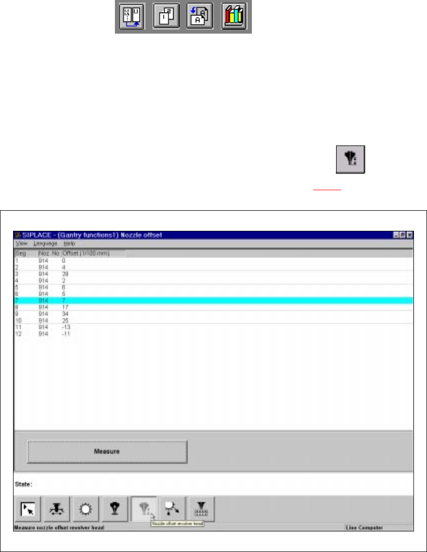
5.2.4 "Nozzle offset" screen
5
Å In the current screen for the single functions for Gantry x, click the symbol .
The user interface is switched to the "Nozzle offset" screen (see Fig. 5.2 - 4
).
5
Fig. 5.2 - 4 "Nozzle offset" screen