OM-1606-006w_GT-28x.pdf - 第134页
OM-1606 6-32 6. Splicing 101 1-003 6.9 44 mm, 56 mm, 72 mm and 88 mm Width T ape Splicing Procedure 6.9.1 Cutting New T ape CAUTION Cut it off with the greatest care so as not to cut your nger . (1) Prepare a new tape. …
OM-1606
6. Splicing
6-310908-001
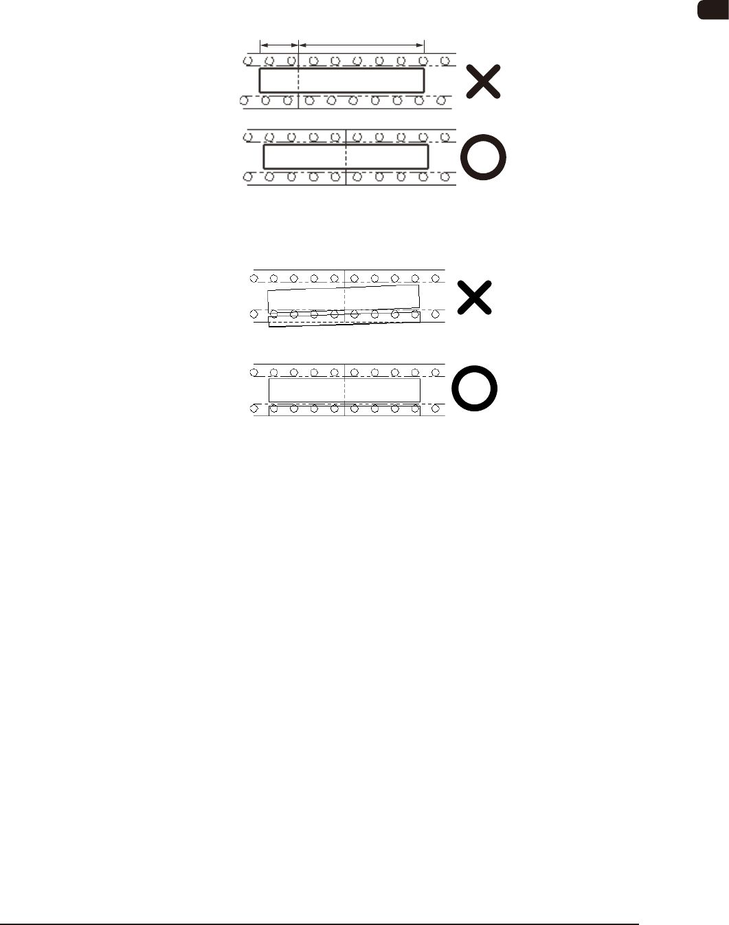
(3) When the splicing tape is adhered, set the center of the cut position of
the splicing tape.
If the tape is deviated along the direction of the splicing tape, the tape
joint section might come off.
Positional Deviation
(4) Do not let the splicing tape swell very far out from the carrier tape.
If there is any swell out, a feed error might occur.
OM-1606
6-32
6. Splicing
1011-003
6.9 44 mm, 56 mm, 72 mm and 88 mm Width Tape Splicing
Procedure
6.9.1 Cutting New Tape
CAUTION
Cut it off with the greatest care so as not to cut your nger.
(1) Prepare a new tape.
Peel off the cover tape up to the
splicing position.
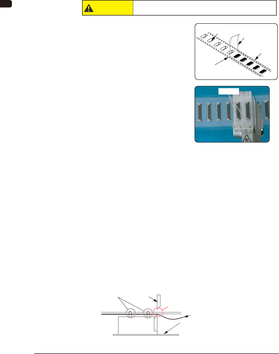
(2) Cut the tape, using the tape cutting
jig.
Set the new tape on the pilot pins so
that the cover tape is turned down.
Then, cut the carrier tape together
with the cover tape.
•
The tape cut jig can deal with tape up
to 32 mm in width. Cut the tape with
a width of 44 or 56 mm, twice.
Otherwise, use scissors if available
and cut it so that the cut position is
not deviated.
•
Take care not to cut any component
in order to prevent damage to the
tape cutting jig.
•
For the tape with the width of 72 or
88 mm, cut it using commercially
available scissors with a blade long
length enough to cut the tape all at
once, so that the cut position does
not deviate.
•
In the case of 12 mm, 20 mm, 28 mm
or 36 mm pitch, the pilot pins are not
used.
There should be no component here.
Mirror Surface
(Make sure that there is no component in
the component compartment hole on the
rear side of the carrier tape).
Pilot Pins
Scissors
Cover Tape
Pilot Pins
Cover Tape
Splicing Position
(Cut Position)
Carrier Tape
Component Compartment
Hole

OM-1606
6. Splicing
6-331005-001
(3) The preparation of new tape has
been completed.