OM-1606-006w_GT-28x.pdf - 第35页
OM-1606 2. Attachment and Detachment of T ape 2-3 (4) Set the tape along the groove. T ape FB5 Notice After removing the adhesive tape xing the cover tape, set the tape. Note If a 16 mm width tape in GT -12162 and GD-12…
OM-1606
2-2
2. Attachment and Detachment of Tape
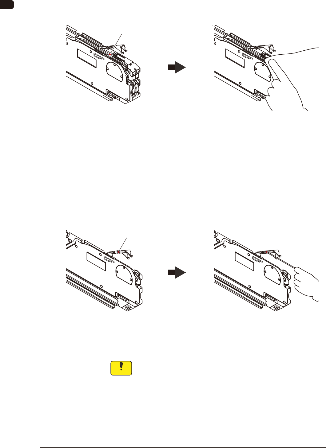
(2) Make sure there is no foreign substance (chip component or dust) on the
chute surface.
If there is any foreign substance on the chute surface, then remove it, using a
rag or air-blow.
Foreign Substance on the Chute Clean it
Chip Component
FB3
When the Magnetic Plate is used, clean it, because a component might be
attached to the magnetic plate.
(3) Make sure there is no foreign substance on the rear surface of the suppressor.
It is very easy for foreign substances to enter the corner section. Therefore,
check it carefully.
If any foreign substance, etc., is attached to the rear surface of the suppressor,
remove it with air-blow, tweezers, or thin bar.
Foreign Substance on the
Rear Surface of the Suppressor
Clean it
Chip Component
FB4
Notice
If the taping component is mounted with any foreign substance
attached, the suppresser might be deformed or a pick-up error
occur.
Therefore, clean it.
1005-002
OM-1606
2. Attachment and Detachment of Tape
2-3
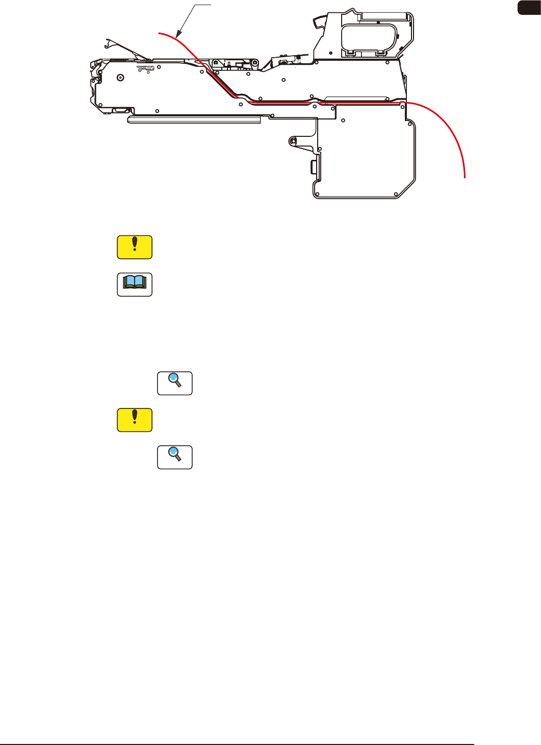
(4) Set the tape along the groove.
Tape
FB5
Notice
After removing the adhesive tape xing the cover tape, set the tape.
Note
If a 16 mm width tape in GT-12162 and GD-12162 or a 32 mm width tape
in GT-24322 and GD-24322 is to be used, then a tape guide and support
suppressor detachments are required.
Also, if a 56 mm width tape in GT-44562 and GD-44562 is to be used,
then a tape guide movement and detachments of support suppressor and
component drop preventive cover are required.
Reference
Refer to "2.5 Tape Guide and Support Suppressor" for details.
Notice
With tape feeders with joint detection units, the tape should be
passed over the joint detection sensor.
Reference
Refer to "2.6 Joint Detection Unit" for how to pass the tape
through the joint detection unit.
1005-002
OM-1606
2-4
2. Attachment and Detachment of Tape
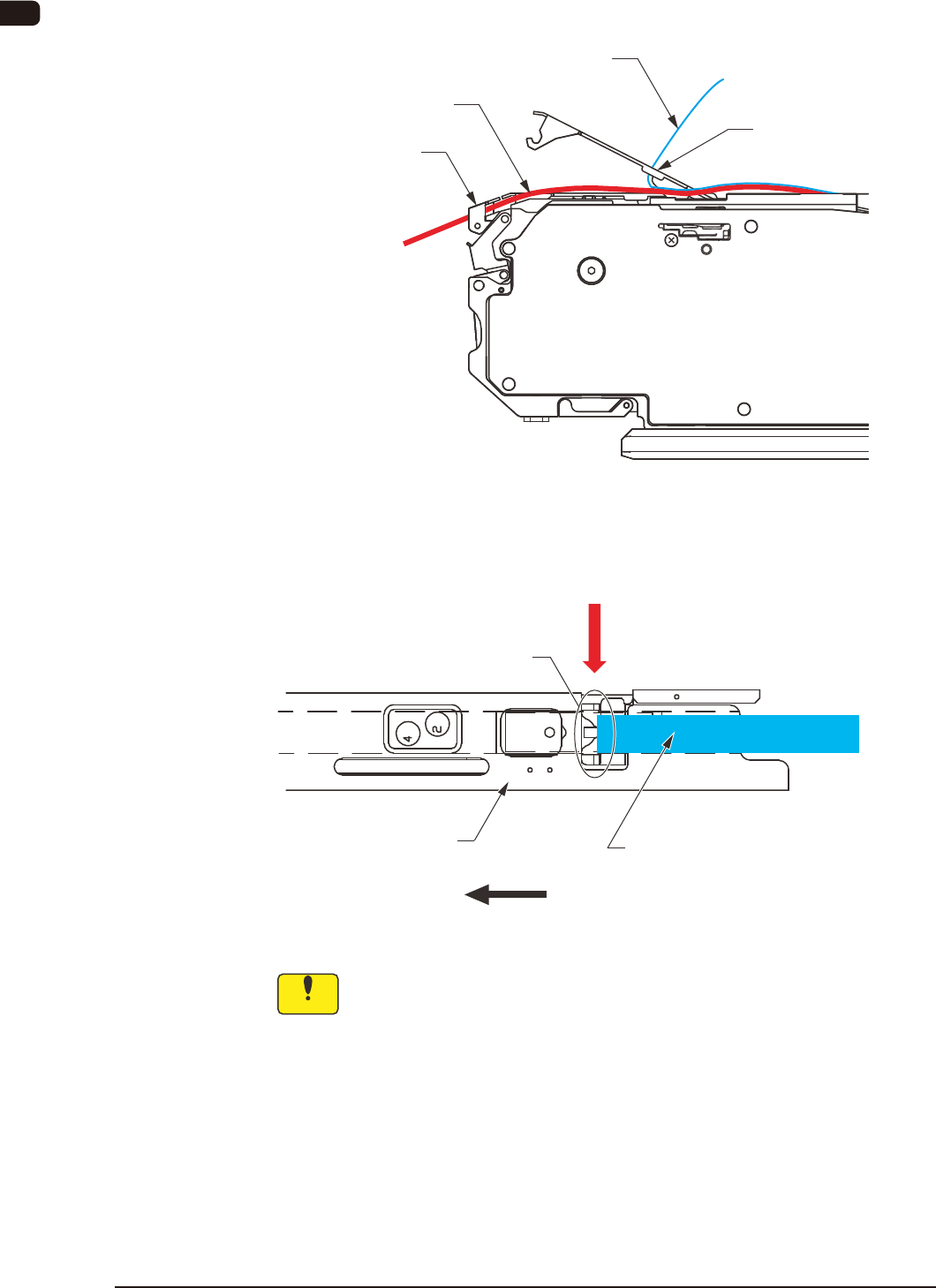
(5) Insert the tape into the tape outlet guide.
(This work is to be performed only for the dual tape feeder with 8 mm
width.)
Cover Tape
Suppressor Peeling
Section
Carrier Tape
Tape Outlet Guide
(Only for 8 mm Width Tape Feeder)
FB6
(6) Pass the cover tape through the slit in the peeling section.
Cover Tape
Direction of Feed
Slit
Suppressor
Pass the cover tape through the slit in the peeling section
FB7
Notice
Do not forcibly pull the cover tape.
0908-001