OM-1606-006w_GT-28x.pdf - 第56页
OM-1606 2-24 2. Attachment and Detachment of T ape (3) Loosen the set screw (hexagon head bolt) to move the tape guide assembly . Tape Guide ASSY Set Screw (Hexagon Head Screw) SECT A-A FB30 Note (a) Attach the tape guid…
OM-1606
2. Attachment and Detachment of Tape
2-23
•
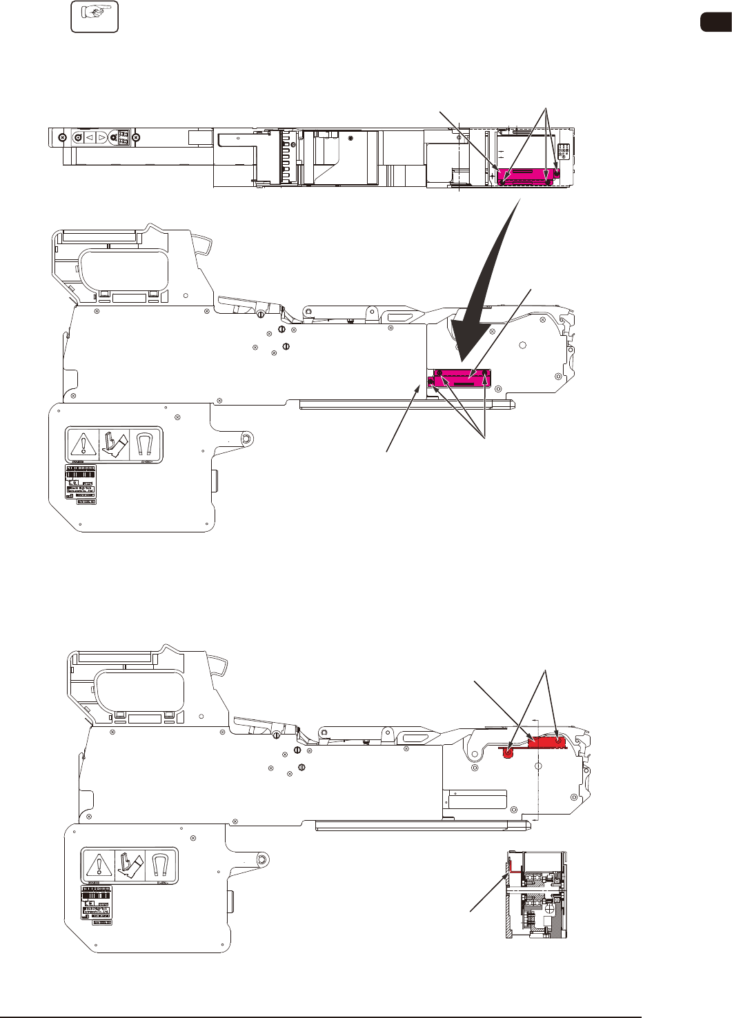
For using tape with 56 mm width
Procedure
(1) Loosen the set screw (round head screw) with a precision screw driver to
remove the support suppressor and attach it onto the support suppressor
housing section.
Set Screw
(Round Head Screw)
Set Screw
(Round Head Screw)
Housing
Support Suppressor
Support Suppressor
Support Suppressor
housing section
FB28
(2) Loosen the set screw (round head screw) to remove the component drop
preventive cover.
SECT A-A
A
A
Set Screw
(Round Head Screw)
Component Drop
Preventive Cover
Component Drop
Preventive Cover
FB29
0908-001
OM-1606
2-24
2. Attachment and Detachment of Tape
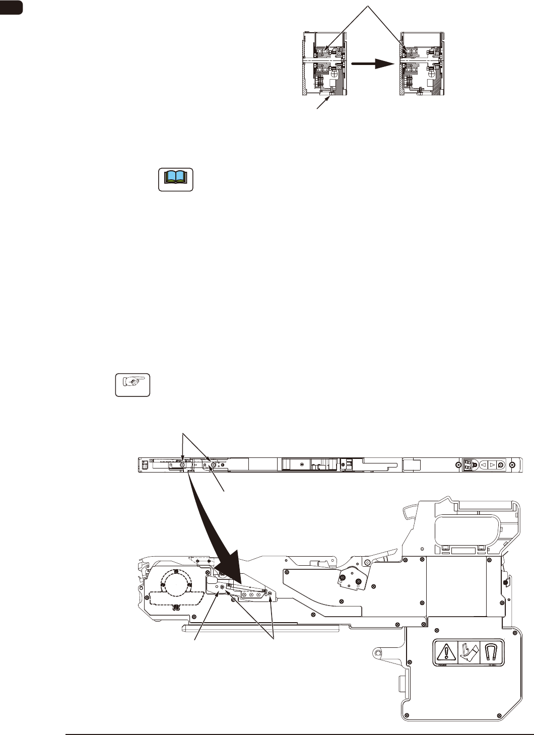
(3) Loosen the set screw (hexagon head bolt) to move the tape guide assembly.
Tape Guide ASSY
Set Screw
(Hexagon Head Screw)
SECT A-A
FB30
Note
(a) Attach the tape guide and support suppressor which are not currently used,
onto each housing section in the tape feeder, not to be lost.
(b) When the tape with 12 mm width is used for GT-12162 or GD-12162,
or the tape with 24 mm width is used for GT-24322 or GD-24322, or the
tape with 44 mm width is used for GT-44562 or DG-44562, use a reverse
procedure to return it.
At the time, fastening torque for the set screws of the tape guide should be
0.59 Nm (6.0 kgf • cm) ± 10 %
2.5.3 Tape Guide Attachment Procedure in Tape Condition where only
one side of the tape comes in contact with the chute
•
For using tape with 12 mm and 16 mm width
Procedure
(1) Remove the set screw (countersunk head screw), and attach it onto the
support suppressor housing section.
Set Screw
(Countersunk Head Screw)
Support Suppressor
housing section
Housing
Tape Guide
Set Screw
(Countersunk Head Screw)
FB31
1005-002
OM-1606
2. Attachment and Detachment of Tape
2-25
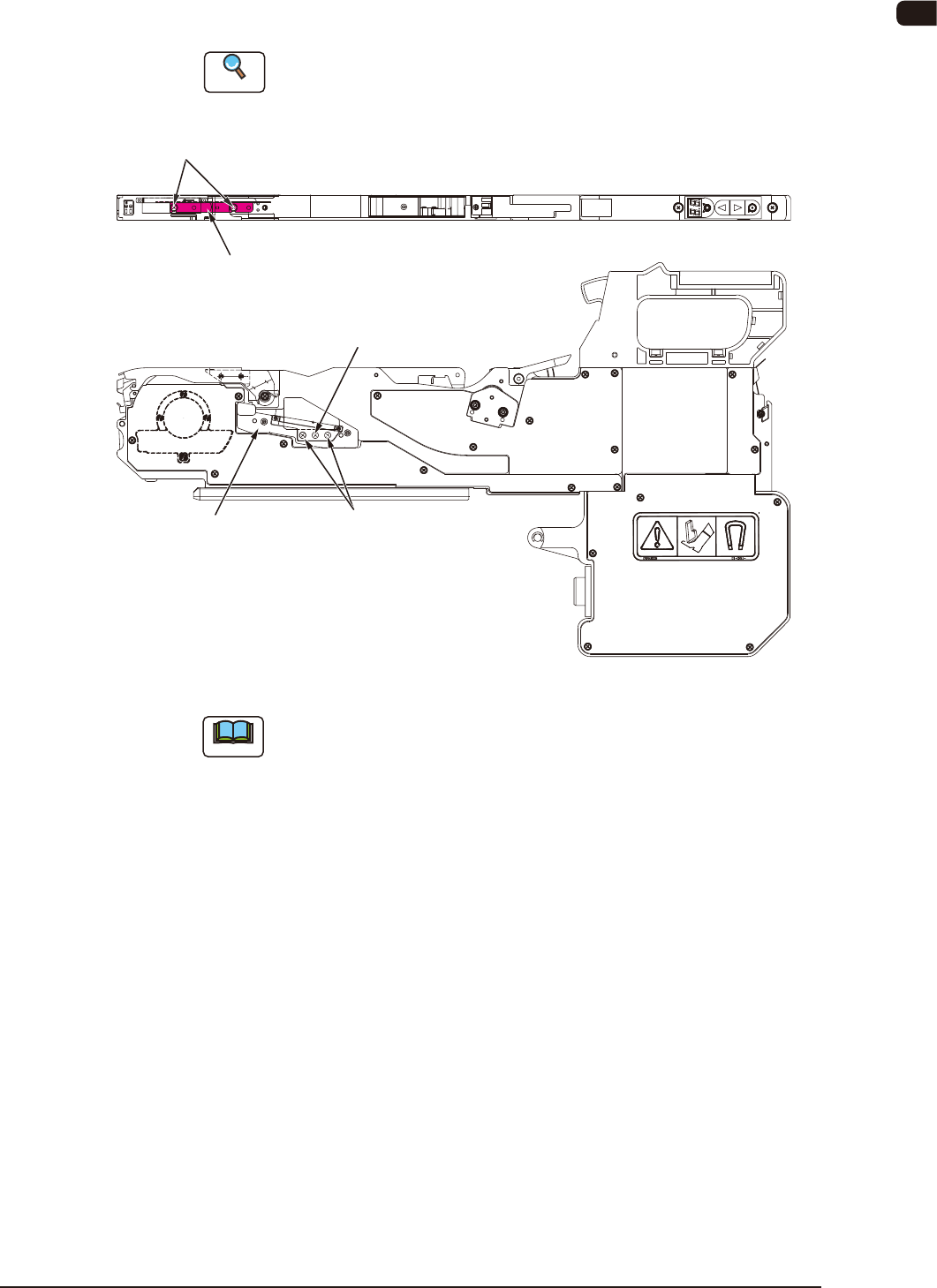
(2) Remove the set screw (round head screw) attached onto the support
suppressor housing section, and attach it onto the tape guide. Then, adjust the
tape guide width based on the emboss pocket width.
Reference
Refer to "2.5 Tape Guide and Support Suppressor" for the tape guide attachment
procedure.
Countersunk Screw
(Note)
Set Screw
(Round Head Screw)
Set Screw
(Round Head Screw)
Support Suppressor
housing section
Tape Guide
FB32
Note
Do not remove the countersunk screw for xing the plate, located between
the round head screws for xing the tape guide.
1005-002