OM-1606-006w_GT-28x.pdf - 第193页
OM-1606 8-10 8. Specications of T ape Feeders 8.3.1 Referential Dimension for T aping Embossed Carrier T ype T aping Embossed Carrier T ype T aping Cover T ape T aped Component (Sprocket Hole) Direction of Unreeling Cov…
OM-1606
8-9
8. Specications of Tape Feeders
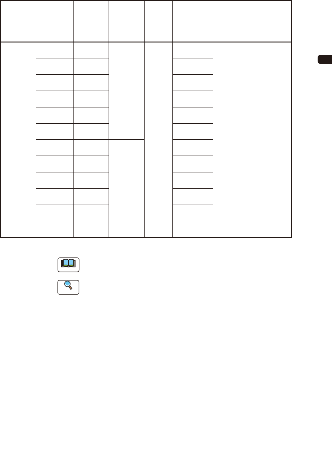
8.3 Specication of 24/32 mm Tape Feeder
Model
Tape Width
×
Feed Pitch
(mm)
Types of
Tape
Standard
Set
Reel Outer
Diameter
×
Width (mm)
Chute
Height
(mm)
Referential
Components
Remarks
GT-24322
GD-24322
24 × 4 Embossed
L : f 382 × 30.4
104.0
• Barcode Label Color :
White
24 × 8 Embossed
24 × 12 Embossed
24 × 16 Embossed
24 × 20 Embossed
24 × 24 Embossed
32 × 4 Embossed
L : f 382 × 38.4
32 × 8 Embossed
32 × 12 Embossed
32 × 16 Embossed
32 × 20 Embossed
32 × 24 Embossed
TH6
Note
If a 32 mm width tape is to be used, then a tape guide and support suppressor
detachments are required.
Reference
Refer to "2.5 Tape Guide and Support Suppressor" for the tape guide and support
suppressor removal procedures.
1005-002
OM-1606
8-10
8. Specications of Tape Feeders
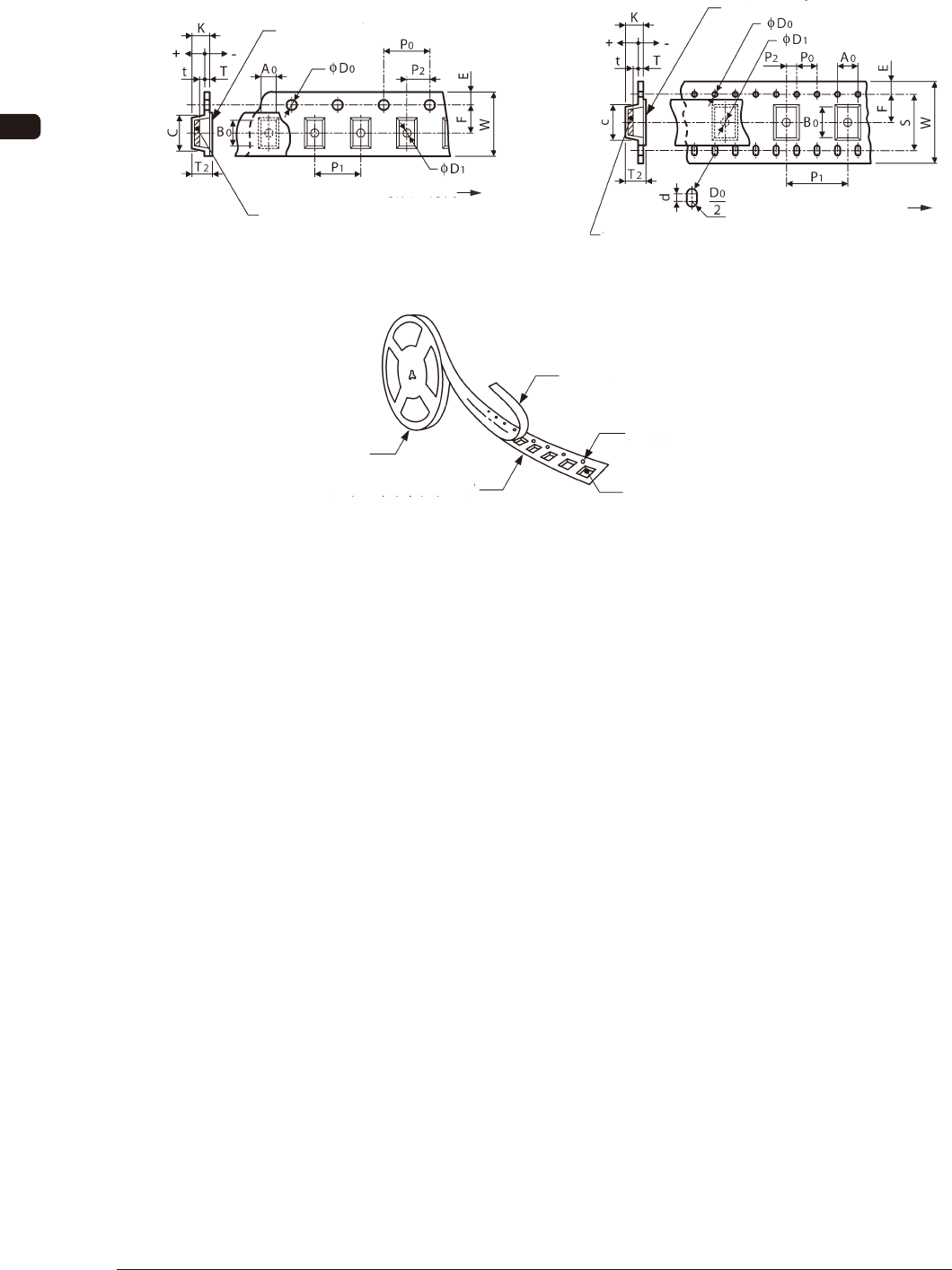
8.3.1 Referential Dimension for Taping
Embossed Carrier Type Taping Embossed Carrier Type Taping
Cover Tape
Taped Component
(Sprocket Hole)
Direction of Unreeling
Cover Tape
Taped Component
(Sprocket Hole)
Direction of Unreeling
Magnified
View
24 mm width FH11 32 mm width FH12
Cover Tape
Sprocket Hole
Reel
Embossed Carrier Tape
Embossed Hole
Component
Compartment
FH13
0908-001
OM-1606
8-11
8. Specications of Tape Feeders
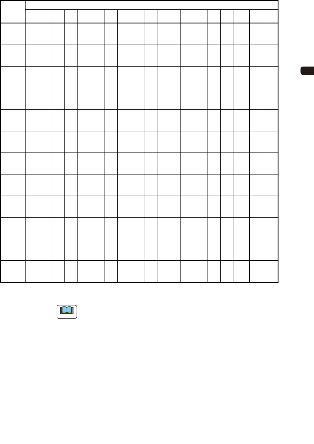
Dimensions for Taping (mm)
Tape Width
×
Feed Pitch
(mm)
A
0
B
0
W F E P
1
P
2
P
0
D
0
T T
2
KD
1
S d C t
24 4
More than
1.6 to 3.4
or less
19.9
or less
24.0
0.3
11.5
0.1
1.75
0.1
4.0
0.1
2.0
0.1
4.0
0.1
1.5
0.1
0
More than
0.3 to 0.6
or less
16.1
or less
16.0
or less
1.5
or more
- -
20.3
or less
1.0
to
- T
(g)
24 8
More than
3.4 to 7.4
or less
19.9
or less
24.0
0.3
11.5
0.1
1.75
0.1
8.0
0.1
2.0
0.1
4.0
0.1
1.5
0.1
0
More than
0.3 to 0.6
or less
16.1
or less
16.0
or less
1.5
or more
- -
20.3
or less
1.0
to
- T
(g)
24 12
More than
7.4 to 10.8
or less
19.9
or less
24.0
0.3
11.5
0.1
1.75
0.1
12.0
0.1
2.0
0.1
4.0
0.1
1.5
0.1
0
More than
0.3 to 0.6
or less
16.1
or less
16.0
or less
1.5
or more
- -
20.3
or less
1.0
to
- T
(g)
24 16
More than
10.8 to 14.6
or less
19.9
or less
24.0
0.3
11.5
0.1
1.75
0.1
16.0
0.1
2.0
0.1
4.0
0.1
1.5
0.1
0
More than
0.3 to 0.6
or less
16.1
or less
16.0
or less
1.5
or more
- -
20.3
or less
1.0
to
- T
(g)
24 20
More than
14.6 to 18.6
or less
19.9
or less
24.0
0.3
11.5
0.1
1.75
0.1
20.0
0.1
2.0
0.1
4.0
0.1
1.5
0.1
0
More than
0.3 to 0.6
or less
16.1
or less
16.0
or less
1.5
or more
- -
20.3
or less
1.0
to
- T
(g)
24 24
More than
18.6 to 22.4
or less
19.9
or less
24.0
0.3
11.5
0.1
1.75
0.1
24.0
0.1
2.0
0.1
4.0
0.1
1.5
0.1
0
More than
0.3 to 0.6
or less
16.1
or less
16.0
or less
1.5
or more
- -
20.3
or less
1.0
to
- T
(g)
32 4
More than
1.6 to 3.4
or less
23.5
or less
32.0
0.3
14.2
0.1
1.75
0.1
4.0
0.1
2.0
0.1
4.0
0.1
1.5
0.1
0
More than
0.3 to 0.6
or less
16.1
or less
16.0
or less
2.0
or more
28.4
0.1
0.2
0.05
24
or less
1.0
to
- T
(g)
32 8
More than
3.4 to 7.4
or less
23.5
or less
32.0
0.3
14.2
0.1
1.75
0.1
8.0
0.1
2.0
0.1
4.0
0.1
1.5
0.1
0
More than
0.3 to 0.6
or less
16.1
or less
16.0
or less
2.0
or more
28.4
0.1
0.2
0.05
24
or less
1.0
to
- T
(g)
32 12
More than
7.4 to 10.8
or less
23.5
or less
32.0
0.3
14.2
0.1
1.75
0.1
12.0
0.1
2.0
0.1
4.0
0.1
1.5
0.1
0
More than
0.3 to 0.6
or less
16.1
or less
16.0
or less
2.0
or more
28.4
0.1
0.2
0.05
24
or less
1.0
to
- T
(g)
32 16
More than
10.8 to 14.6
or less
23.5
or less
32.0
0.3
14.2
0.1
1.75
0.1
16.0
0.1
2.0
0.1
4.0
0.1
1.5
0.1
0
More than
0.3 to 0.6
or less
16.1
or less
16.0
or less
2.0
or more
28.4
0.1
0.2
0.05
24
or less
1.0
to
- T
(g)
32 20
More than
14.6 to 18.6
or less
23.5
or less
32.0
0.3
14.2
0.1
1.75
0.1
20.0
0.1
2.0
0.1
4.0
0.1
1.5
0.1
0
More than
0.3 to 0.6
or less
16.1
or less
16.0
or less
2.0
or more
28.4
0.1
0.2
0.05
24
or less
1.0
to
- T
(g)
32 24
More than
18.6 to 22.4
or less
23.5
or less
32.0
0.3
14.2
0.1
1.75
0.1
24.0
0.1
2.0
0.1
4.0
0.1
1.5
0.1
0
More than
0.3 to 0.6
or less
16.1
or less
16.0
or less
2.0
or more
28.4
0.1
0.2
0.05
24
or less
1.0
to
- T
(g)
TH7
Note
(a) A
0
×
B
0
stands for the rectangle hole size on the tape.
The clearance between a rectangle hole and a component affects the pick-
up rate.
Use the taping component with appropriate clearance specications.
(b) The above specications do not imply any guarantee of pick-up rate, etc.
The pick-up rate varies depending on how the main machine is adjusted
and the combination of the main machine and the tape feeders.
(c) Make a hole (D
1
) in the cavity if necessary.
(d) 10 pitches cumulative tolerance P
0
should be ± 0.2 mm.
(e) The cover tape should run smoothly along the sprocket holes.
The edges of the cover tape should be aligned with the carrier tape (taping).
The thickness of the cover tape should be 0.07 mm or less (including waste
paper).
0908-001