OM-1606-006w_GT-28x.pdf - 第184页
OM-1606 8-1 8. Specications of T ape Feeders 8. Specications of T ape Feeders 8.1 Specications of 8 mm Dual T ape Feeder Model T ape Width × Feed Pitch (mm) T ypes of T ape Standard Set Reel Outer Diameter × Width (mm…

OM-1606
7-33
7. Maintenance
1011-001
OM-1606
8-1
8. Specications of Tape Feeders
8. Specications of Tape Feeders
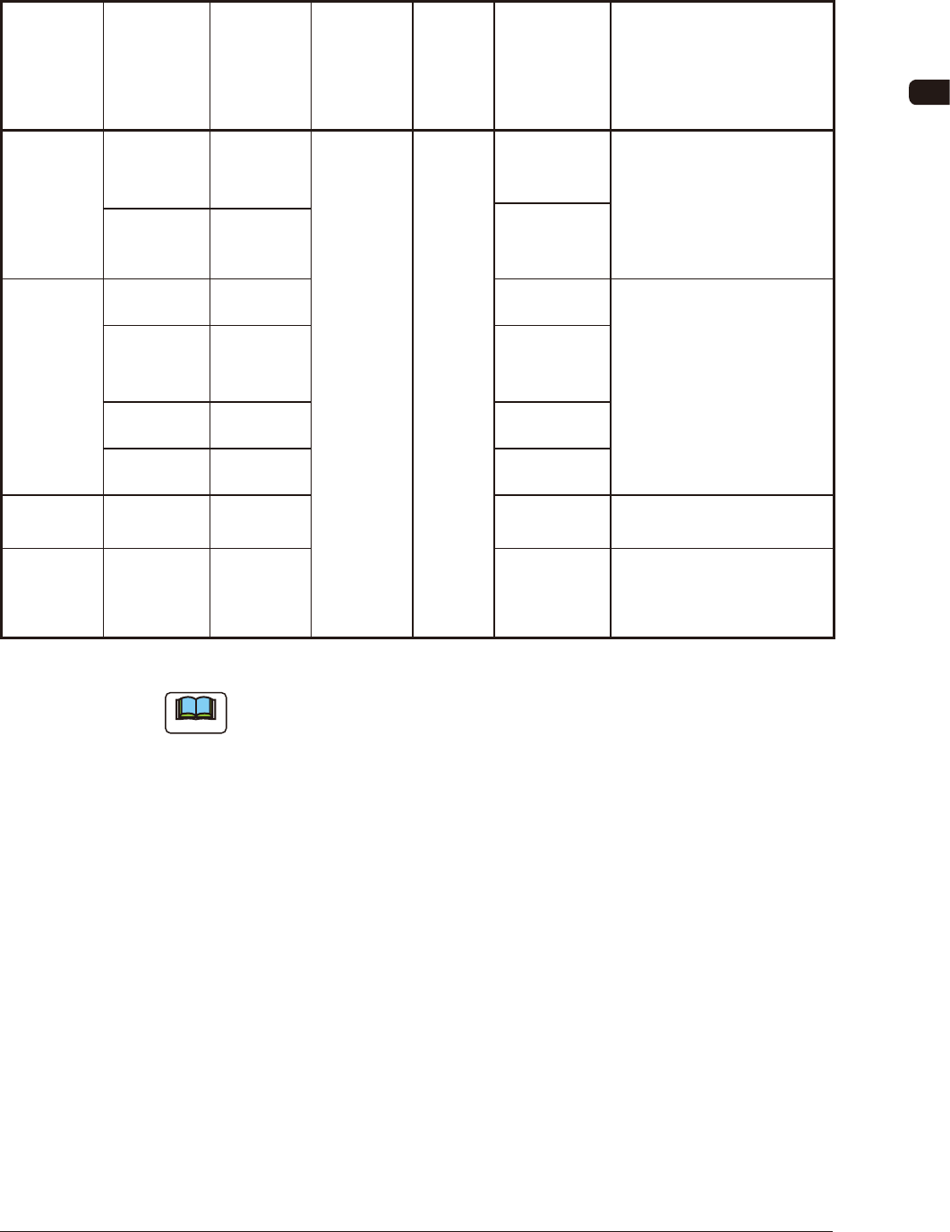
8.1 Specications of 8 mm Dual Tape Feeder
Model
Tape Width
×
Feed Pitch
(mm)
Types of
Tape
Standard
Set
Reel Outer
Diameter
×
Width (mm)
Chute
Height
(mm)
Referential
Components
Remarks
GD-28081
8 × 2 Paper
L : f 382 × 14.4
S : f 178 × 14.4
104.0
0603
• 0603, 1005
• Barcode Label Color :
Yellow + White
1005
8 × 2 Embossed
GT-28080
GD-28080
8 × 2 Paper 1005
• Barcode Label Color :
White
8 × 4 Paper
2012
3216
3225
8 × 2 Embossed
8 × 4 Embossed
GT-28082
GD-28082
8 × 8 Embossed
• Barcode Label Color :
Pink + White
GD-28083
8 × 2 Paper 0402
• Exclusive for 0402
• Barcode Label Color :
Blue + White
TH1
Note
The sizes of the components entitled "Referential Components" differ depending
on the component makers.
The components are shown as types for your reference.
0908-001
OM-1606
8-2
8. Specications of Tape Feeders
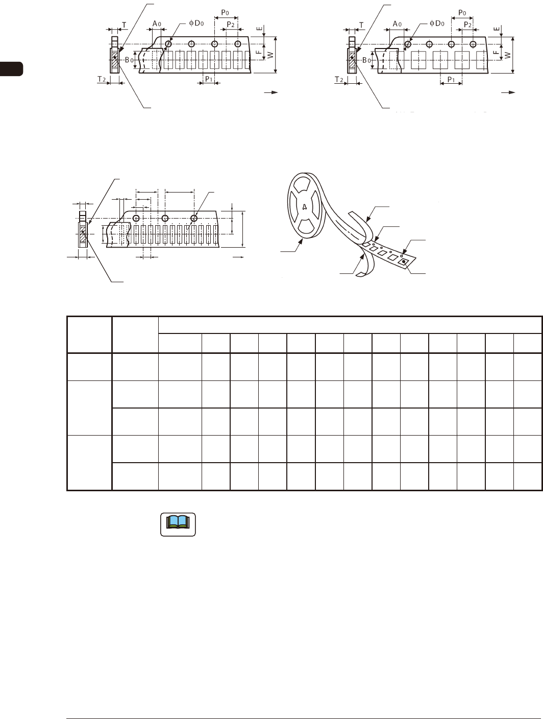
8.1.1 Referential Dimension for Taping (8 mm Paper)
Rectangle Hole Punched Carrier Type Taping Rectangle Hole Punched Carrier Type Taping
Cover Tape
Taped Component
Direction of Unreeling
(Sprocket Hole)
Cover Tape
Taped Component
(Sprocket Hole)
Direction of Unreeling
Rectangle Hole Pitch (2 mm) FH1 Rectangle Hole Pitch (4 mm) FH2
Rectangle Hole Punched Carrier Type Taping
P
2
P
1
T
2
T
A
0
B
0
P
0
φ
D
0
(Sprocket
Hole)
Direction of Unreeling
Taped Component
Cover Tape
F E
W
P
3
P
4
Cover Tape
Rectangle Punched Carrier Tape
Sprocket Hole
Rectangle Hole Component
Compartment
Reel
Bottom Cover Tape
Rectangle Hole Pitch (1 mm) FH3 FH3-1
Model
Tape Width
×
Feed Pitch
(mm)
Dimensions for Taping (mm)
A
0
B
0
W F E P
1
P
2
P
3
P
4
P
0
D
0
T T
2
GD-28081 8 × 2
More than
0.3 to 0.7
or less
1.2
or less
8.0
± 0.1
3.5
± 0.05
1.75
± 0.1
2.0
± 0.05
2.0
± 0.05
- -
4.0
± 0.05
f 1.5
+ 0.1
0
0.6
or less
0.6
or less
GT-28080
GD-28080
8 × 2
More than
0.5 to 0.8
or less
1.2
or less
8.0
± 0.1
3.5
± 0.05
1.75
± 0.1
2.0
± 0.05
2.0
± 0.05
- -
4.0
± 0.1
f 1.5
+ 0.1
0
0.7
or less
0.7
or less
8 × 4
More than
0.8 to 3.4
or less
4.3
or less
8.0
± 0.1
3.5
± 0.05
1.75
± 0.1
4.0
± 0.1
2.0
± 0.05
- -
4.0
± 0.1
f 1.5
+ 0.1
0
1.1
or less
1.1
or less
GD-28083
8 × 1
More than
0.2 to 0.7
or less
0.5
or less
8.0
± 0.1
3.5
± 0.05
1.75
± 0.05
1.0
± 0.05
1.0
± 0.05
2.0
± 0.05
3.0
± 0.05
4.0
± 0.05
f 1.5
+ 0.1
0
0.6
or less
0.6
or less
8 × 2
(0402)
More than
0.2 to 0.3
or less
0.5
or less
8.0
± 0.1
3.5
± 0.05
1.75
± 0.05
2.0
± 0.05
2.0
± 0.05
- -
4.0
± 0.05
f 1.5
+ 0.1
0
0.4
or less
0.4
or less
TH2
Note
(a) A
0
×
B
0
stands for the rectangle hole size on the tape.
The clearance between a rectangle hole and a component affects the pick-
up rate.
Use the taping component with appropriate clearance specications.
(b) The above specications do not imply any guarantee of pick-up rate, etc.
The pick-up rate varies depending on how the main machine is adjusted
and the combination of the main machine and the tape feeders.
(c) The clearance between the centerlines of the cavity and the sprocket hole
should be 0.05 mm or less.
(d) 10 pitches cumulative tolerance P
0
should be ± 0.2 mm.
1009-002