OM-1606-006w_GT-28x.pdf - 第96页
OM-1606 4-18 4. Operation Panel 0908-001
OM-1606
4-17
4. Operation Panel
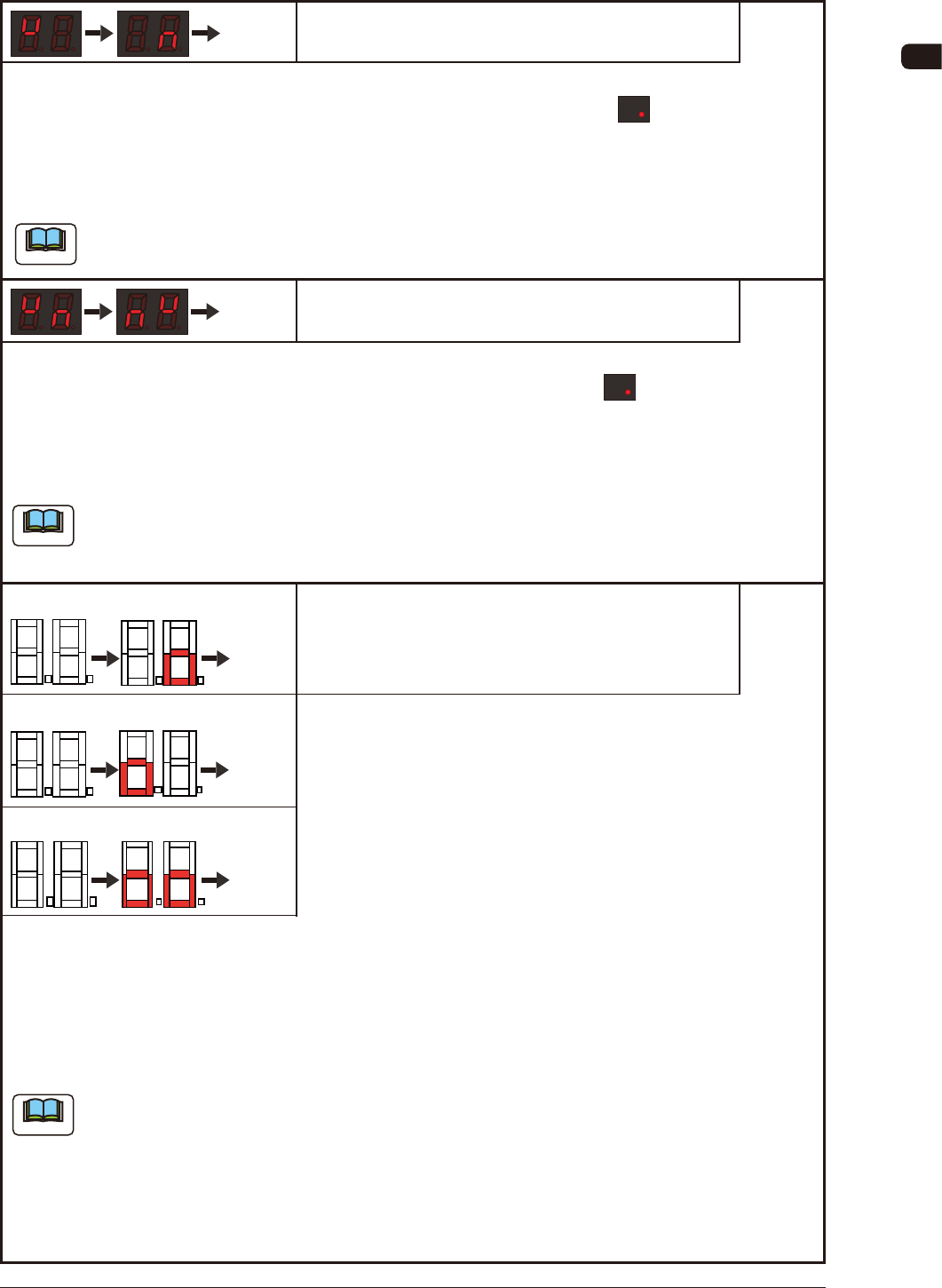
The lane for which a splicing alarm is output is displayed with dot indication .
This alarm shows the splicing timing for supplemental components, based on the number of
components remaining.
Note
This is the rst alarm to advance the splicing preparation, and the pick-up of the components on the
subjected lane is continued after the alarm.
Splicing Alarm
Repeated
The lane for which a splicing stop is output is displayed with dot indication .
It shows the second stage to which the mode has been transferred "Stop for Splicing" : the component
pick-up is stopped on that lane while the tape end required for splicing is secured.
Note
If the pick-up operation is continued after the splicing alarm is output for promoting the preparation
of component supply, the tape end of the reel being currently used would enter inside the feeder and
the splicing operation can not be performed.
Stop for Splicing
Repeated
4.3.3 Splicing Guide
Cover Tape Housing Section FULL Alarm
Lane 1 FULL Alarm
Repeating
Repeating
Repeating
Lane 2 FULL Alarm
Lane 1 and 2 FULL Alarm
This alarm is to notify that the cover tape housing section is almost lled with the peeled-off cover
tape.
Open the cover of the cover tape housing section for which the cover tape housing section FULL alarm
is issued, and collect the cover tape. If cover tape is left as it is, without collecting it, the cover of the
housing section is opened and the cover tape comes out from it.
Note
In the following cases, the alarm can not be issued correctly due to the cover tape FULL alarm
detection processing method.
•
Tape feed speed has been set to "Deceleration".
•
The feed pitch amount is small.
•
The cover tape peeling off strength is large.
•
The cover tape viscosity is large.
0907-001

OM-1606
4-18
4. Operation Panel
0908-001
OM-1606
5-1
5. Component Pick-up Position Alignment
0908-001
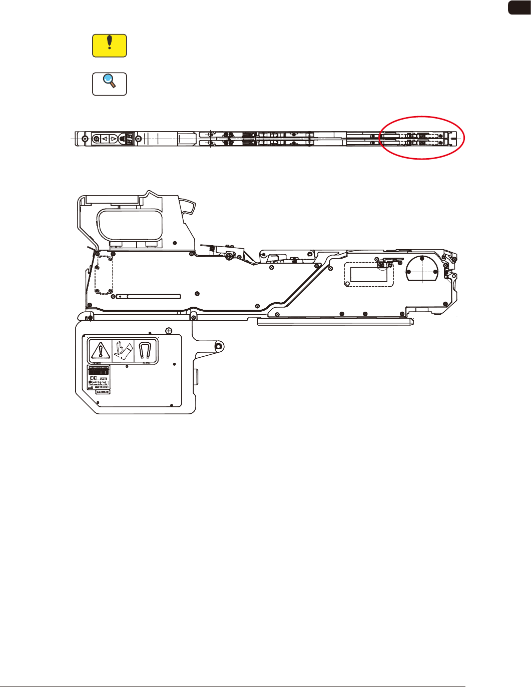
5. Component Pick-up Position Alignment
To pick up a component correctly, the component center is aligned with the pick-
up position.
The component center set position is marked on the suppressor.
Also, the pick-up position varies with the pitch of the feed.
Notice
If the component center is not aligned with the pick-up position, then the
pick-up cannot proceed correctly.
Reference
Refer to "4.2.4 Minimum Pitch Feed Operation" for the tape feeding operation.
Suppressor
FE1