OM-1606-006w_GT-28x.pdf - 第37页
OM-1606 2. Attachment and Detachment of T ape 2-5 • For GT -44562, GT -72002, GD-44562, GD-72002 Normally, set the cover tape through the slit on the peeling section as shown in the following gure. Slit in the Peeling S…
OM-1606
2-4
2. Attachment and Detachment of Tape
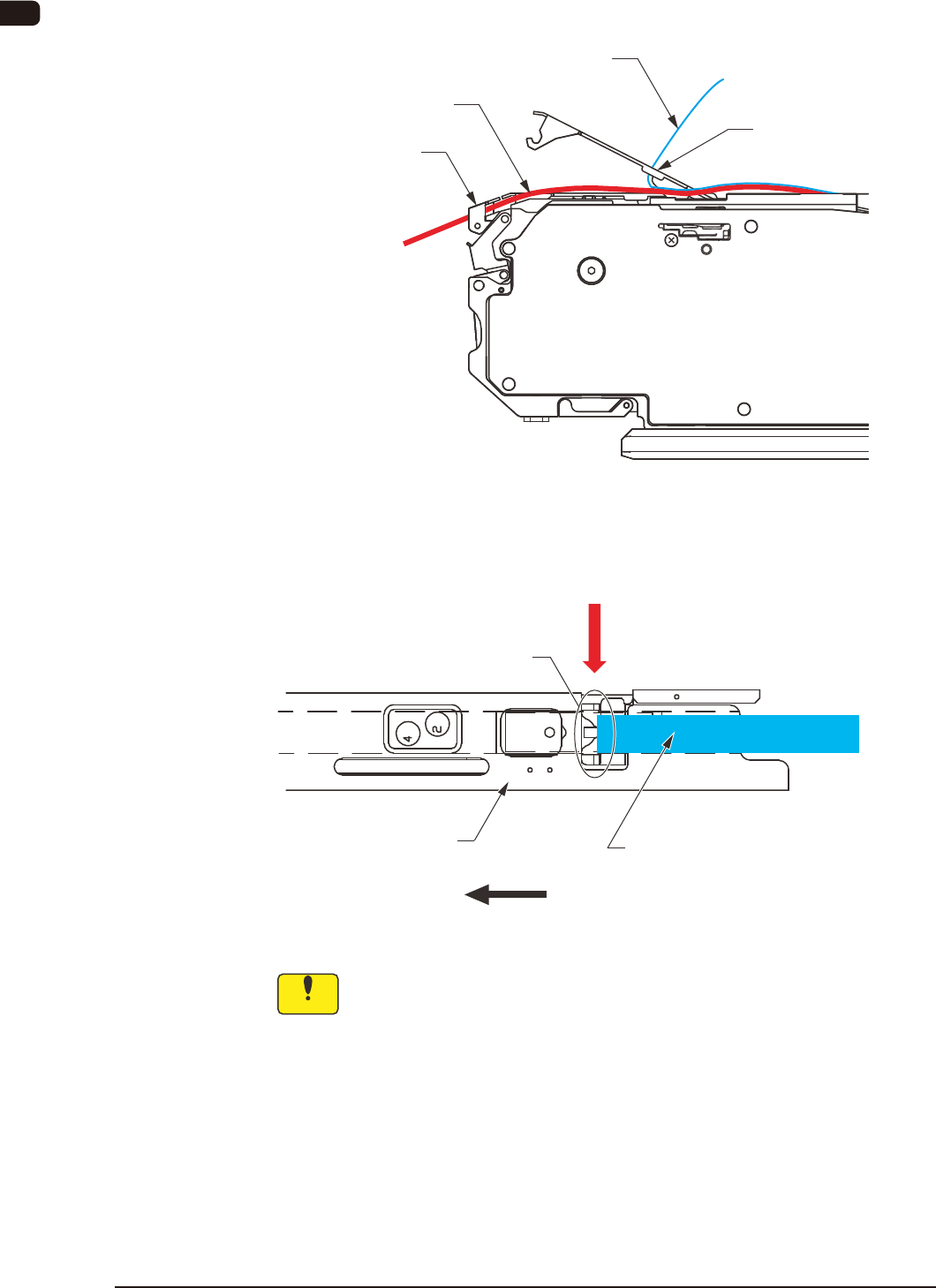
(5) Insert the tape into the tape outlet guide.
(This work is to be performed only for the dual tape feeder with 8 mm
width.)
Cover Tape
Suppressor Peeling
Section
Carrier Tape
Tape Outlet Guide
(Only for 8 mm Width Tape Feeder)
FB6
(6) Pass the cover tape through the slit in the peeling section.
Cover Tape
Direction of Feed
Slit
Suppressor
Pass the cover tape through the slit in the peeling section
FB7
Notice
Do not forcibly pull the cover tape.
0908-001
OM-1606
2. Attachment and Detachment of Tape
2-5
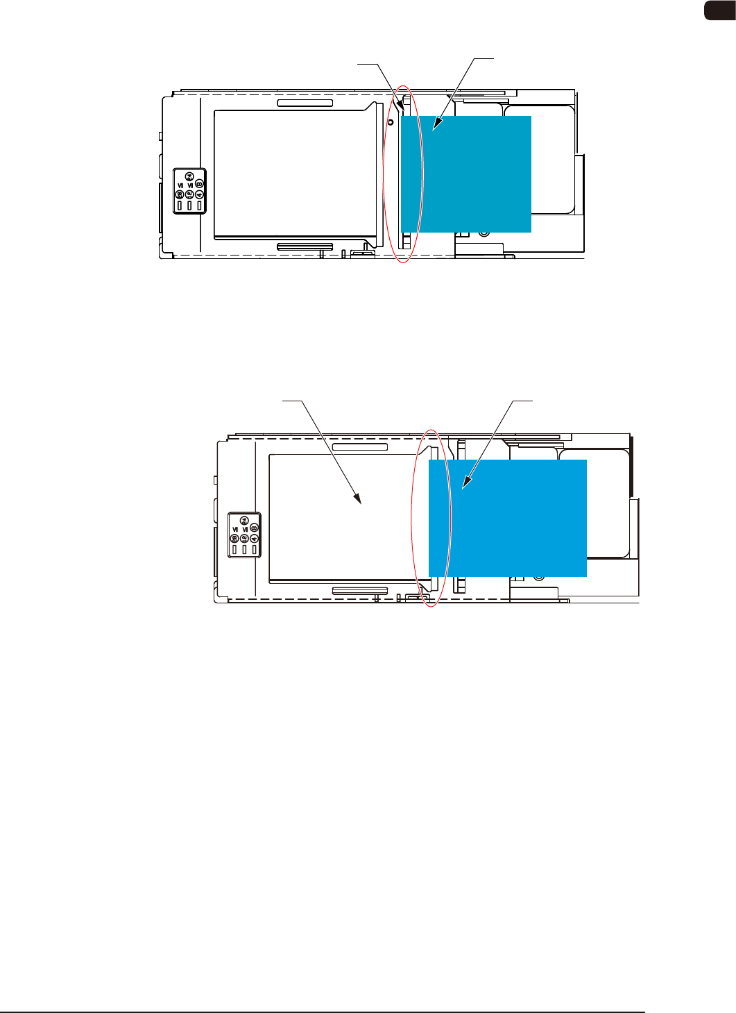
•
For GT-44562, GT-72002, GD-44562, GD-72002
Normally, set the cover tape through the slit on the peeling section as shown in the
following gure.
Slit in the Peeling Section
Cover Tape
FB8
In the case that a component body or component electrode section is projecting
from the tape surface due to the taping deformation, set the cover tape through the
pick-up aperture section as shown in the following gure.
Pick-up Aperture Section
Cover Tape
FB9
1011-002
OM-1606
2-6
2. Attachment and Detachment of Tape
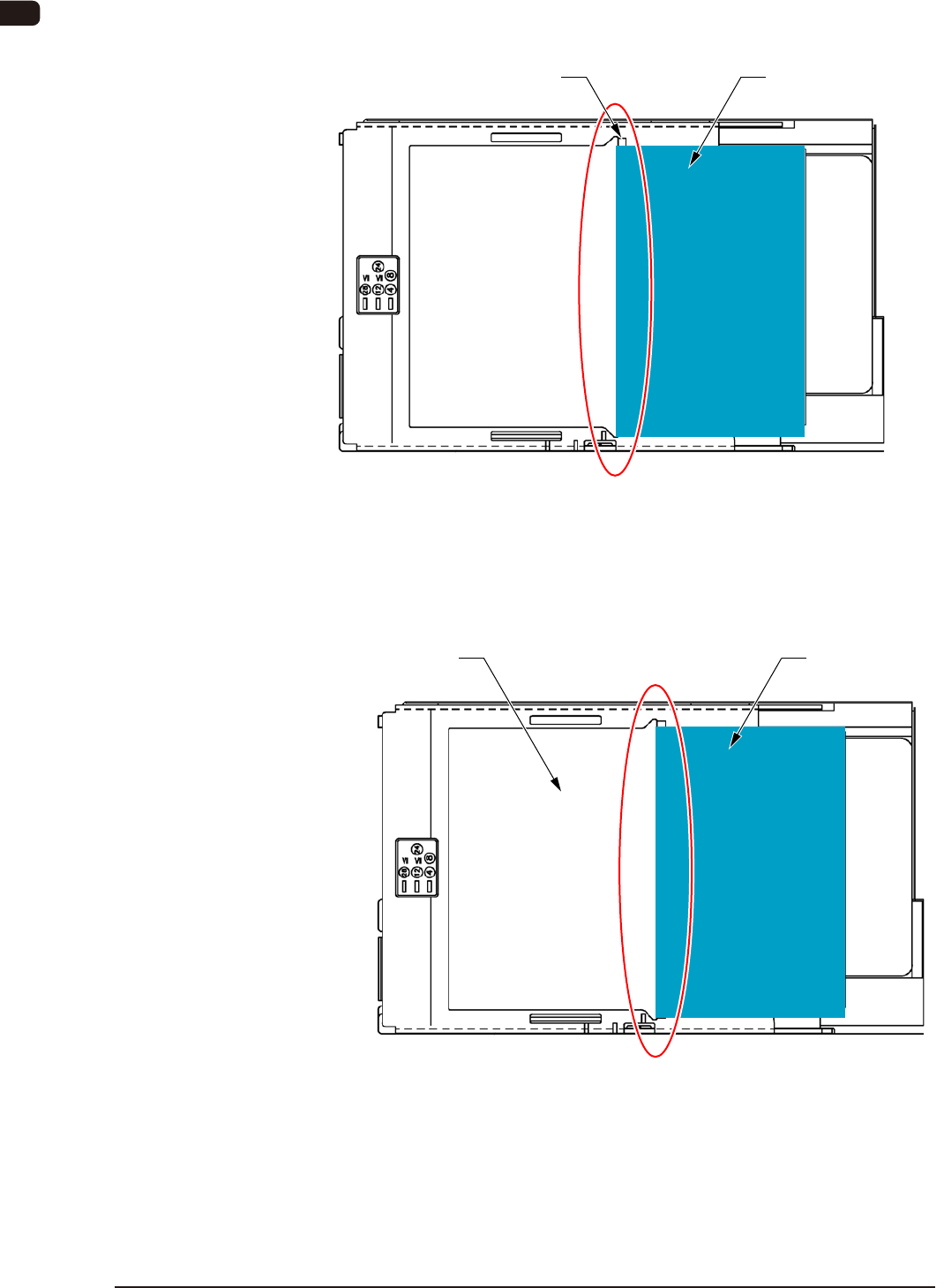
•
For GT-88002, GD-88002
Normally, set the cover tape through the slit on the peeling section as shown in the
following gure.
Slit in the Peeling Section
Cover Tape
FB9-1
In the case that a component body or component electrode section is projecting
from the tape surface due to the taping deformation, set the cover tape through the
pick-up aperture section as shown in the following gure.
Pick-up Aperture Section
Cover Tape
FB9-2
1011-002