OM-1606-006w_GT-28x.pdf - 第31页
OM-1606 1. Scope 1-5 0908-001 [1] Suppressor Feeding of the tape and releasing of the cover tape are performed smoothly by pressing the cover tape against the chute. During the operation, take care so that no foreign sub…
OM-1606
1-4
1. Scope
1.2 Name and Function of Each Section
It is described in GT-28080 (8 mm Dual Tape Feeder)
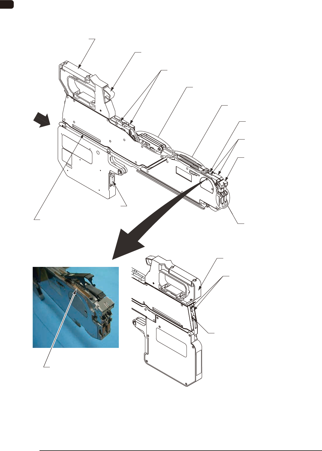
[8] Clamp Cancel Lever
[2] Tape Outlet Guide
[6] Cover Tape Tension Lever
[7] Cover Tape Take-up Release Lever
[1] Suppressor
[5] Chute
[3] Front Hook
[4] Sprocket
[12] Cover Tape Outlet Cover
[13] Cutter
[10] Connector
[9] Operation Panel
[11] Barcode Label
[15] Magnetic Plate Housing Section
[14] Magnetic Plate
View
View
FA3
0908-001

OM-1606
1. Scope
1-50908-001
[1] Suppressor
Feeding of the tape and releasing of the cover tape are performed smoothly
by pressing the cover tape against the chute.
During the operation, take care so that no foreign substance (chip component
or debris) is attached.
Two units are attached onto the dual tape feeder with 8 mm width.
A single unit is attached onto the dual tape feeder with 12 mm width or
more.
[2] Tape Outlet Guide
This guide discharges the tape.
This guide is attached only onto the dual tape feeder with 8 mm width.
[3] Front Hook
This hook holds the suppressor.
Two units are attached onto the dual tape feeder with 8 mm width.
A single unit is attached onto the dual tape feeder with 12 mm width or
more.
[4] Sprocket
This engages with the sprocket hole on the tape to feed the specied pitches
of the tape.
[5] Chute
This is the tape running surface close to pick-up position.
During the operation, take care so that no foreign substance (chip component
or debris) is attached.
Two units are attached onto the dual tape feeder with 8 mm width.
A single unit is attached onto the dual tape feeder with 12 mm width or
more.
[6] Cover Tape Tension Lever
Guides the released cover tape to the cover tape housing section.
[7] Cover Tape Tale-up Release Lever
This button is pressed when the cover tape is set to or taken from the cover
tape housing section.
Two units are attached onto the dual tape feeder with 8 mm width.
A single unit is attached onto the dual tape feeder with 12 mm width or
more.

OM-1606
1-6
1. Scope
0908-001
[8] Clamp Release Lever
This button is pressed when the tape feeder is removed from the bank feeder
change cart.
[9] Operation Panel
Shows the various settings or status of the tape feeder.
Reference
Refer to "4. Operation Panel" for details.
[10] Connector
This connector conducts electricity and electrical signals.
[11] Barcode Label
Barcodes are printed for tape feeder model, serial No. and ACV system.
[12] Cover Tape Outlet Cover
This is the cover on the cover tape housing section.
This cover is opened when the cover tape is taken out from the cover tape
housing section.
Two units are attached onto the dual tape feeder with 8 mm width.
A single unit is attached onto the dual tape feeder with 12 mm width or
more.
[13] Cutter
This cutter cuts off the cover tape taken from the cover tape housing section.
[14] Magnetic Plate
It is attached to the chute section.
Using magnetic force, the component pick-up operation is stabilized.
It is attached only onto the dual tape feeder with 8 mm width or 12 mm
width.
[15] Magnetic Plate Housing Section
When the Magnetic Plate is not to be used, it is stored in this housing space.
It is attached only onto the dual tape feeder with 8 mm width or 12 mm
width.