OM-1606-006w_GT-28x.pdf - 第186页
OM-1606 8-3 8. Specications of T ape Feeders (e) The cover tape should run smoothly along the sprocket holes. The edges of the cover tape should be aligned with the carrier tape (taping). The thickness of the cover tape…
OM-1606
8-2
8. Specications of Tape Feeders
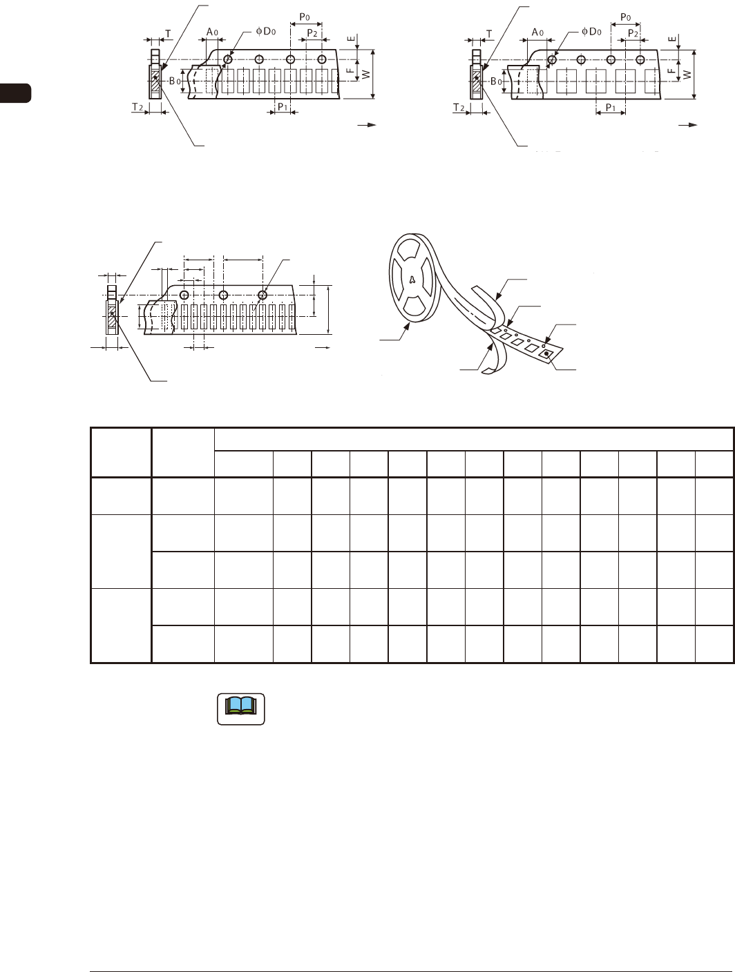
8.1.1 Referential Dimension for Taping (8 mm Paper)
Rectangle Hole Punched Carrier Type Taping Rectangle Hole Punched Carrier Type Taping
Cover Tape
Taped Component
Direction of Unreeling
(Sprocket Hole)
Cover Tape
Taped Component
(Sprocket Hole)
Direction of Unreeling
Rectangle Hole Pitch (2 mm) FH1 Rectangle Hole Pitch (4 mm) FH2
Rectangle Hole Punched Carrier Type Taping
P
2
P
1
T
2
T
A
0
B
0
P
0
φ
D
0
(Sprocket
Hole)
Direction of Unreeling
Taped Component
Cover Tape
F E
W
P
3
P
4
Cover Tape
Rectangle Punched Carrier Tape
Sprocket Hole
Rectangle Hole Component
Compartment
Reel
Bottom Cover Tape
Rectangle Hole Pitch (1 mm) FH3 FH3-1
Model
Tape Width
×
Feed Pitch
(mm)
Dimensions for Taping (mm)
A
0
B
0
W F E P
1
P
2
P
3
P
4
P
0
D
0
T T
2
GD-28081 8 × 2
More than
0.3 to 0.7
or less
1.2
or less
8.0
± 0.1
3.5
± 0.05
1.75
± 0.1
2.0
± 0.05
2.0
± 0.05
- -
4.0
± 0.05
f 1.5
+ 0.1
0
0.6
or less
0.6
or less
GT-28080
GD-28080
8 × 2
More than
0.5 to 0.8
or less
1.2
or less
8.0
± 0.1
3.5
± 0.05
1.75
± 0.1
2.0
± 0.05
2.0
± 0.05
- -
4.0
± 0.1
f 1.5
+ 0.1
0
0.7
or less
0.7
or less
8 × 4
More than
0.8 to 3.4
or less
4.3
or less
8.0
± 0.1
3.5
± 0.05
1.75
± 0.1
4.0
± 0.1
2.0
± 0.05
- -
4.0
± 0.1
f 1.5
+ 0.1
0
1.1
or less
1.1
or less
GD-28083
8 × 1
More than
0.2 to 0.7
or less
0.5
or less
8.0
± 0.1
3.5
± 0.05
1.75
± 0.05
1.0
± 0.05
1.0
± 0.05
2.0
± 0.05
3.0
± 0.05
4.0
± 0.05
f 1.5
+ 0.1
0
0.6
or less
0.6
or less
8 × 2
(0402)
More than
0.2 to 0.3
or less
0.5
or less
8.0
± 0.1
3.5
± 0.05
1.75
± 0.05
2.0
± 0.05
2.0
± 0.05
- -
4.0
± 0.05
f 1.5
+ 0.1
0
0.4
or less
0.4
or less
TH2
Note
(a) A
0
×
B
0
stands for the rectangle hole size on the tape.
The clearance between a rectangle hole and a component affects the pick-
up rate.
Use the taping component with appropriate clearance specications.
(b) The above specications do not imply any guarantee of pick-up rate, etc.
The pick-up rate varies depending on how the main machine is adjusted
and the combination of the main machine and the tape feeders.
(c) The clearance between the centerlines of the cavity and the sprocket hole
should be 0.05 mm or less.
(d) 10 pitches cumulative tolerance P
0
should be ± 0.2 mm.
1009-002
OM-1606
8-3
8. Specications of Tape Feeders
(e) The cover tape should run smoothly along the sprocket holes.
The edges of the cover tape should be aligned with the carrier tape (taping).
The thickness of the cover tape should be 0.07 mm or less (including waste
paper).
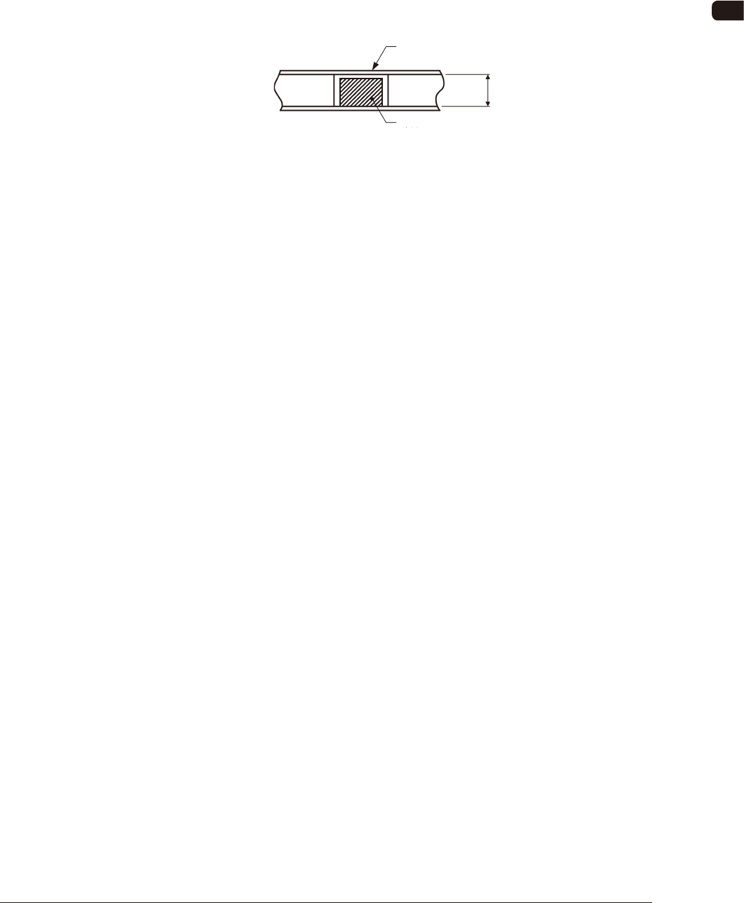
(f) Use a taping on condition that the component itself or its electrical contact
is not protruded from the upper surface of tape.
Paper Taping
"Tape thickness (T) > Component thickness"
Cover Tape
Component
T
FH4
(g) The shape of component pick-up surface should be wide and smooth
enough to be picked up by vacuum nozzles.
(h) Cover tapes sometimes become thicker than expected due to leafy and
uffy leftovers produced through the production process.
However, the overall thickness should not exceed the value described as
"T
2
" in the table.
1009-002
OM-1606
8-4
8. Specications of Tape Feeders
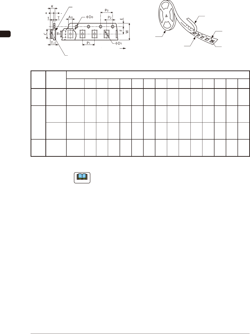
8.1.2 Referential Dimension for Taping (8 mm Embossed)
Embossed Carrier Type Taping
Cover Tape
Taped Component
(Sprocket Hole)
Direction of Unreeling
Cover Tape
Sprocket Hole
Reel
Embossed Carrier Tape
Embossed Hole
Component
Compartment
FH5 FH6
Model
Tape Width
×
Feed Pitch
(mm)
Dimensions for Taping (mm)
A
0
B
0
W F E P
1
P
2
P
0
D
0
T T
2
K D
1
C t
GD-28081
8 × 2
More than
0.3 to 0.7
or less
1.2
or less
8.0
± 0.1
3.5
± 0.05
1.75
± 0.1
2.0
± 0.05
2.0
± 0.05
4.0
± 0.05
f 1.5
+ 0.1
0
0.3
or less
2.5
or less
2.4
or less
0.5
or more
3.0
or less
+0.2
to
- T
(g)
GT-28080
GD-28080
8 × 2
1.6 or less
2.5
or less
8.0
± 0.1
3.5
± 0.05
1.75
± 0.1
2.0
± 0.1
2.0
± 0.05
4.0
± 0.1
f 1.5
+ 0.1
0
0.3
or less
2.5
or less
2.4
or less
0.5
or more
3.0
or less
+0.2
to
- T
(g)
8 × 4
More than
1.6 to
3.4 or less
4.3
or less
8.0
± 0.3
3.5
± 0.05
1.75
± 0.1
4.0
± 0.1
2.0
± 0.05
4.0
± 0.1
f 1.5
+ 0.1
0
0.3
or less
2.5
or less
2.4
or less
0.5
or more
4.5
or less
+0.2
to
- T
(g)
GD-28082
8 × 8
More than
3.4 to 7.4
or less
4.3
or less
8.0
± 0.3
3.5
± 0.05
1.75
± 0.05
8.0
± 0.1
2.0
± 0.05
4.0
± 0.1
f 1.5
+ 0.1
0
0.3
or less
2.5
or less
2.4
or less
0.5
or more
4.5
or less
+0.2
to
- T
(g)
TH3
Note
(a) A
0
×
B
0
stands for the rectangle hole size on the tape.
The clearance between a rectangle hole and a component affects the pick-
up rate.
Use the taping component with appropriate clearance specications.
(b) The above specications do not imply any guarantee of pick-up rate, etc.
The pick-up rate varies depending on how the main machine is adjusted
and the combination of the main machine and the tape feeders.
(c) Make a hole (D
1
) in the cavity if necessary.
(d) 10 pitches cumulative tolerance P
0
should be ± 0.2 mm.
(e) The cover tape should run smoothly along the sprocket holes.
The edges of the cover tape should be aligned with the carrier tape (taping).
The thickness of the cover tape should be 0.07 mm or less (including waste
paper).
1005-002