OM-1606-006w_GT-28x.pdf - 第58页
OM-1606 2-26 2. Attachment and Detachment of T ape • For using tape with 24 mm width Procedure (1) Remove the set screw (countersunk head screw), and attach it onto the set screw housing section. Set Screw (Countersunk H…
OM-1606
2. Attachment and Detachment of Tape
2-25
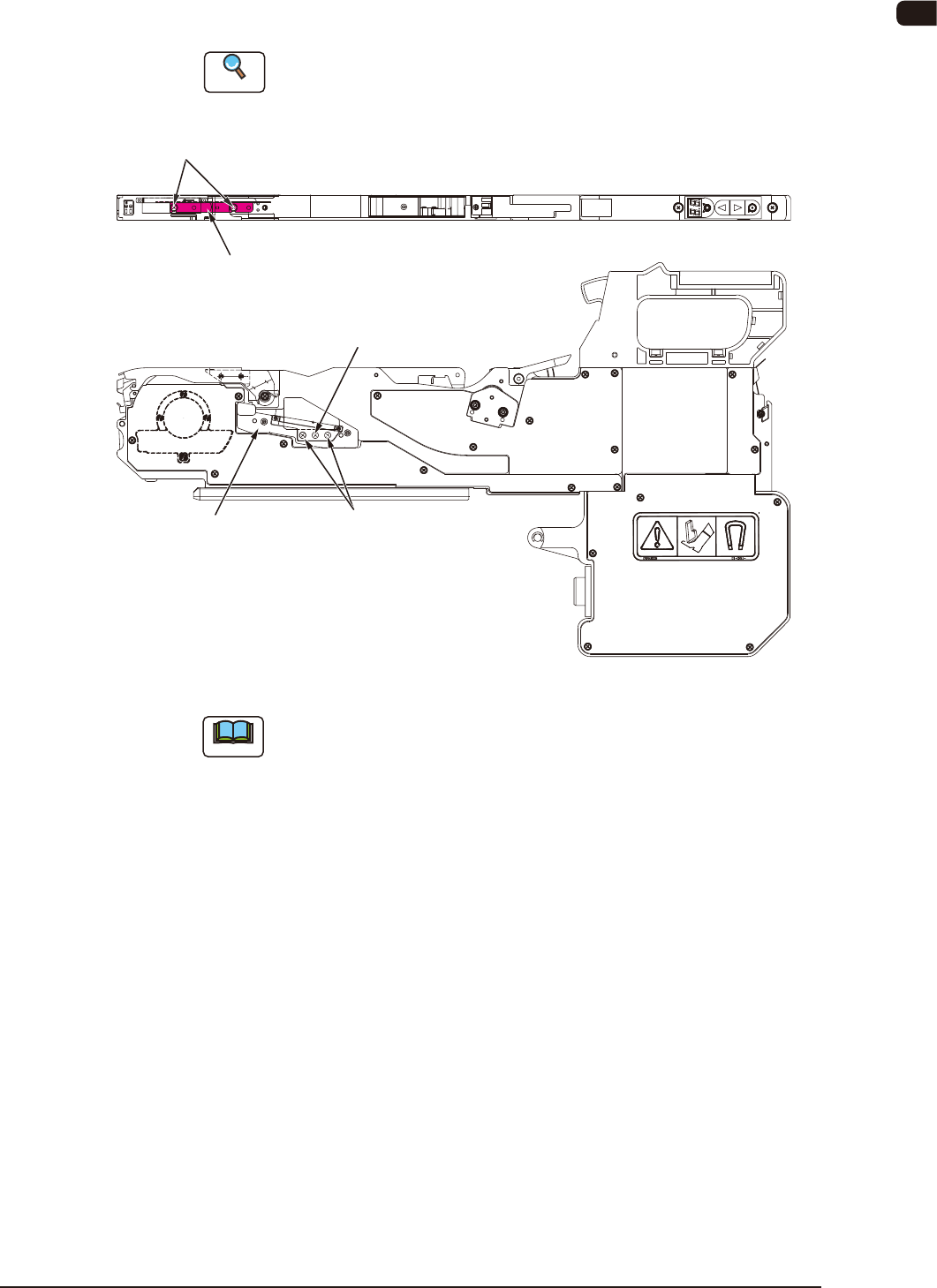
(2) Remove the set screw (round head screw) attached onto the support
suppressor housing section, and attach it onto the tape guide. Then, adjust the
tape guide width based on the emboss pocket width.
Reference
Refer to "2.5 Tape Guide and Support Suppressor" for the tape guide attachment
procedure.
Countersunk Screw
(Note)
Set Screw
(Round Head Screw)
Set Screw
(Round Head Screw)
Support Suppressor
housing section
Tape Guide
FB32
Note
Do not remove the countersunk screw for xing the plate, located between
the round head screws for xing the tape guide.
1005-002
OM-1606
2-26
2. Attachment and Detachment of Tape
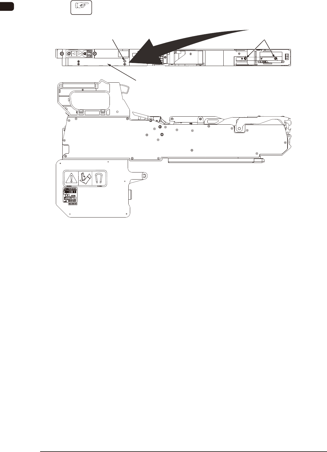
•
For using tape with 24 mm width
Procedure
(1) Remove the set screw (countersunk head screw), and attach it onto the set
screw housing section.
Set Screw
(Countersunk Head Screw)
Set Screw
(Countersunk Head Screw)
Set Screw housing section
Housing
FB33
0908-001
OM-1606
2. Attachment and Detachment of Tape
2-27
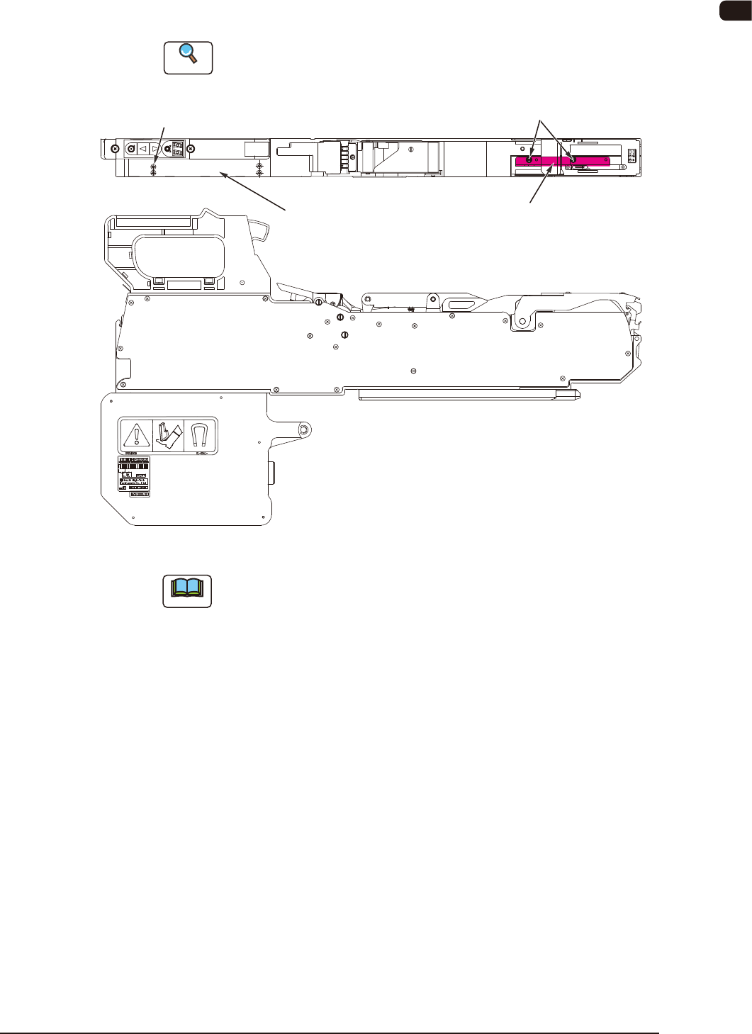
(2) Remove the set screw (round head screw) attached onto the set screw
housing section, and attach it onto the tape guide. Then, adjust the tape guide
width based on the emboss pocket width.
Reference
Refer to "2.5.1 Description of Tape Guide" for the tape guide attachment
procedure.
Tape Guide
Set Screw
(Round Head Screw)
Set Screw
(Round Head Screw)
Set Screw housing section
FB34
Note
For a 32 mm width tape, the tape guide is not available.
When a 32 mm width tape is to be used, make sure to remove the tape
guide.
1005-002