OM-1606-006w_GT-28x.pdf - 第165页
OM-1606 7-15 7. Maintenance (5) Apply grease onto the left worm gear and wheel. Apply grease directly onto the left worm gear and wheel through the right sprocket hole using the greasing jig (The amount to be applied sho…
OM-1606
7-14
7. Maintenance
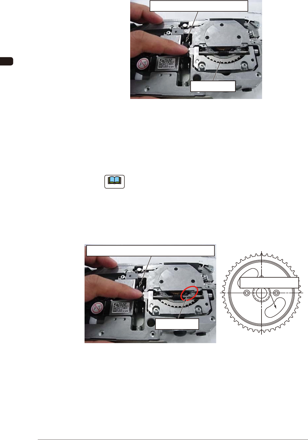
Apply grease turning the timing belt.
Right Sprocket
FG15
In greasing, turn the sprocket and apply grease little by little so that grease is
applied uniformly.
When the timing belt is turned by your nger as shown in FG15, the sprocket
is turned.
(During one turn of the sprocket, apply grease on about 4 locations).
Note
(a) Do not remove the timing belt.
(b) Do not apply grease on the timing belt.
(4) Apply grease on the left worm gear.
Turn the timing belt and arrange the sprocket so that the hole of the right
sprocket is aligned to the position shown in the circle in the gure,
(so that the hole can be seen from the left worm gear or wheel).
Move the hole by means of turning the timing belt.
Aligning Position
Right Sprocket Hole
FG16
0908-001
OM-1606
7-15
7. Maintenance
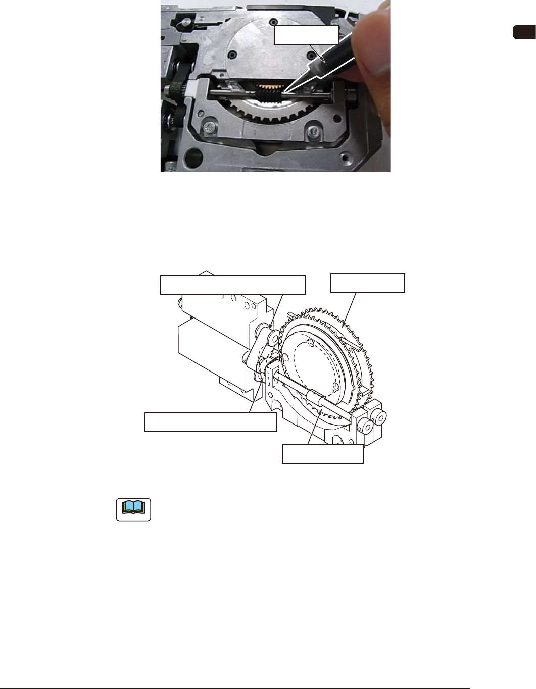
(5) Apply grease onto the left worm gear and wheel.
Apply grease directly onto the left worm gear and wheel through the right
sprocket hole using the greasing jig (The amount to be applied should be
about 0.2 ml (two divisions on the gauge)).
Greasing Jig
FG17
In greasing, turn the sprocket and apply grease little by little so that grease is
applied uniformly.
(During one turn of the sprocket, apply grease on about 4 locations).
Right Sprocket
Left Sprocket Timing Belt
Left Sprocket
Right Sprocket Timing Belt
FG18
Note
(a) Do not remove the timing belt.
(b) Do not apply grease on the timing belt.
(6) Attach the dust preventive cover and right side cover.
Attach the removed dust preventive cover and right side cover. Then, the
work has been completed.
0908-001
OM-1606
7-16
7. Maintenance
7.5.2 8 mm Dual Feeder Joint Detection Unit Sensor Section Cleaning
(GD-28080, GD-28081, GD-28082, GD-28083)
7.5.2.1 Spots to be Cleaned
Clean dust and debris stuck to the sensor section inside the joint detection unit.
There is one sensor section each on the right and left lanes. Clean both of them.
Note
Without cleaning, the sensor does not function normally and an error might be
caused in the detection of spliced joint (When dust is attached, the machine
might be in the condition where it is always detecting the spliced joint).
Sensor Section
(One Location each on the Right and Left)
FG19
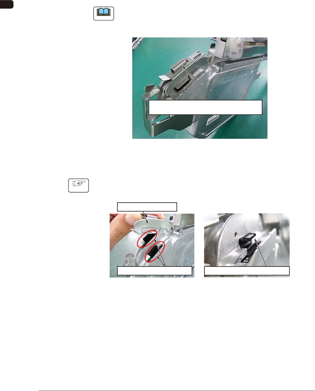
7.5.2.2 How to Clean the Sensor Section
Procedure
(1) Lift the tape holding cover to expose the sensor, and clean the gap in the
sensor section.
Expose the Sensor Section.
Clean the Gap in the Sensor Section.
Tape Holding Cover
FG20
0908-001