OM-1606-006w_GT-28x.pdf - 第210页
OM-1606 9-1 9. Reference T aping Specications 9. Reference T aping Specications 9.1 Allowable Limit of Edge W aving of T ape Allowable limit of edge waving of tape should be or less than 1 mm per 100 mm through a lengt…

OM-1606
8-26
8. Specications of Tape Feeders
1011-001
OM-1606
9-1
9. Reference Taping Specications
9. Reference Taping Specications
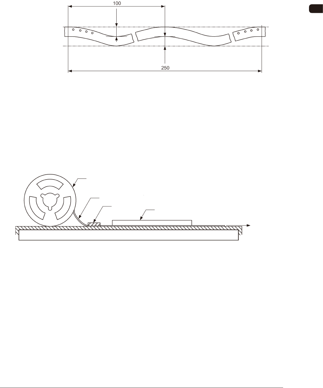
9.1 Allowable Limit of Edge Waving of Tape
Allowable limit of edge waving of tape should be or less than 1 mm per 100 mm
through a length of 250 mm as illustrated.
1 or less
1 or less
Unit : mm
Allowable Limit of Edge Waving of Tape FI1
9.2 Test Method for Edge Waving of Tape
The edge waving of tape shall be tested in such a manner that one end of tape
is xed, the tape is pulled by a force of 1N (102 gf) applied to the other end, a
graduated transparent plastic plate which also serves as a weight is placed on the
tape, and then the waving is measured.
Tape
Reel
Fixed Point
Graduated transparent plastic plate
which also serves as weight
Force of 1N
(102 gf)
Test Method for Edge Waving of Tape FI2
0908-001
OM-1606
9-2
9. Reference Taping Specications
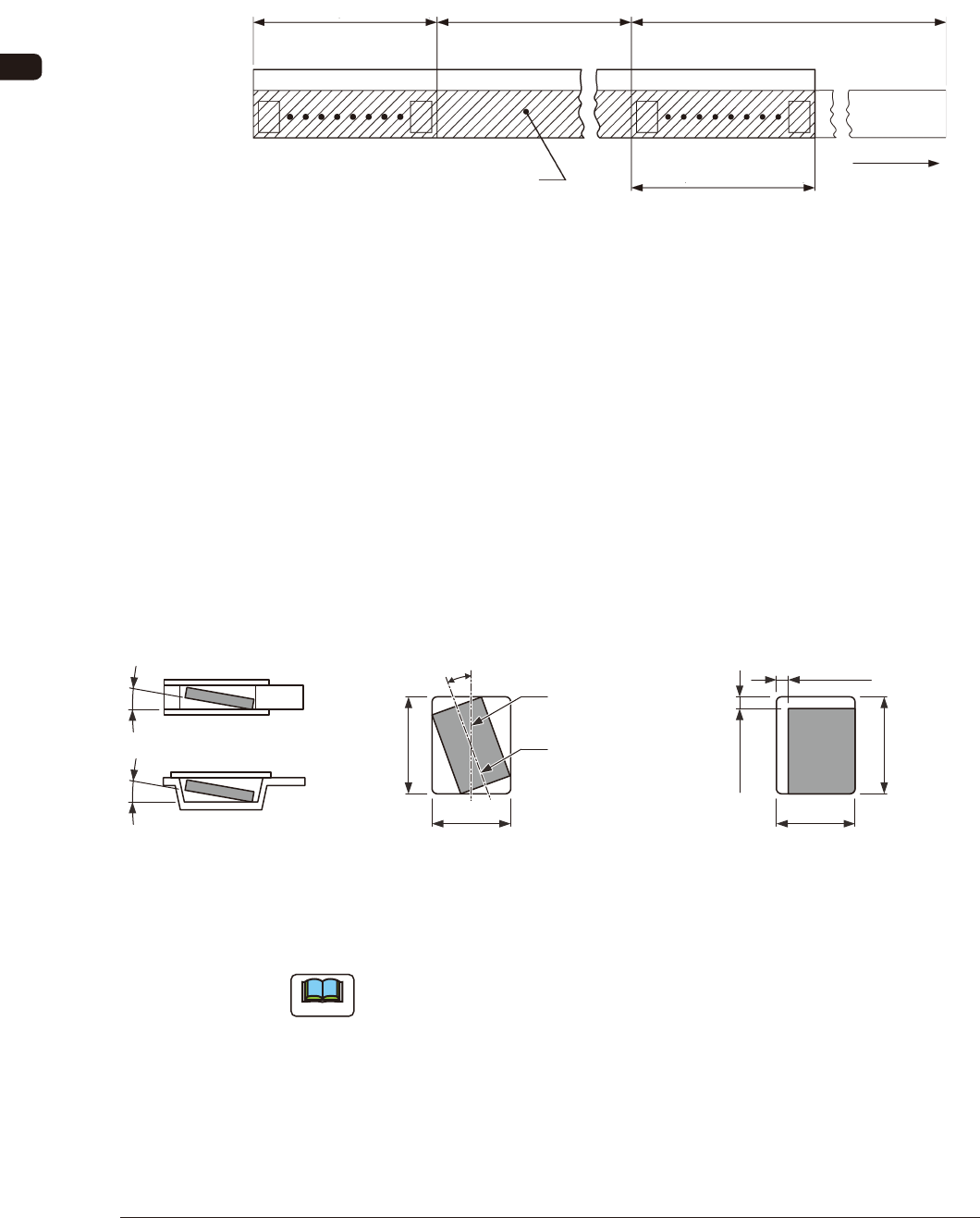
9.3 Leader Section (Tape End Section)
The tape length in the leader section should be 400 mm or more including the
empty component compartment. Such empty component compartment should be
sealed with a cover tape for 100 mm or more.
Trailer (160 mm min.)
Portion Equipped with Surface
Mounting Component
Leader (400 mm min.)
Cover Tape
Empty Component
Compartment
Empty Component
Compartment
(100 mm min. Seal)
Direction of Unreeling
FI3
9.4 Trailer Section (Tape Trailer Section)
The tape length of the trailer section should be 160 mm or more including the
empty component compartment.
The empty component compartment should be sealed with a cover tape.
The last portion of carrier tape shall release from the reel hub.
9.5 Position of Taped Component
B
0
Center Line of
Component Compartment
Center Line of
Component
(Note)
20° or less (Tape Width 8, 12 mm)
10° or less (Tape Width 16 mm min)
Top ViewSide Sectional View or
Front Sectional View
Component Revolution in
Horizontal Direction
Component Inclination
10° or less10° or less
B0
A0
(Note)
0.5 mm or less
(Tape Width 8 to 24 mm)
1.0 mm or less
(Tape Width 32 to 72 mm)
(Note)
0.5 mm or less
(Tape Width 8 to 24 mm)
1.0 mm or less
(Tape Width 32 to 72 mm)
Top View
Component Bias in
Horizontal Direction
A0
FI4
Note
When the direction of a component is changed in the square punched hole or
embossed tape hole, the component can not be picked up easily. In such case,
keep an appropriate clearance around the component in the hole.
0908-001