OM-1606-006w_GT-28x.pdf - 第30页
OM-1606 1-4 1. Scope 1.2 Name and Function of Each Section It is described in GT -28080 (8 mm Dual T ape Feeder) [8] Clamp Cancel Lever [2] T ape Outlet Guide [6] Cover T ape T ension Lever [7] Cover T ape T ake-up Relea…
OM-1606
1. Scope
1-3
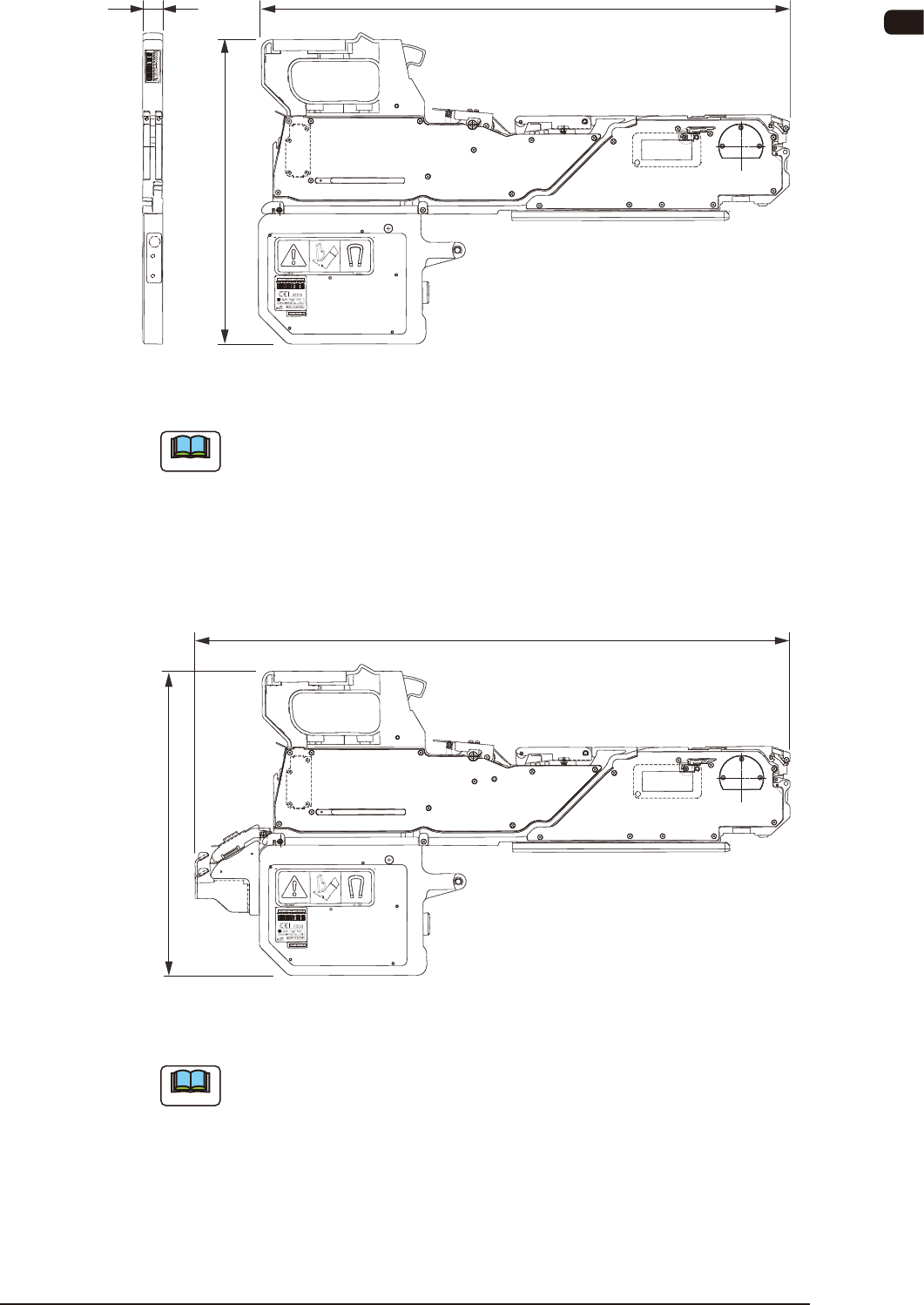
538
W
315
Unit : mm
8 mm Dual Tape Feeder FA1
Note
The total width (W) of each tape feeder are as follows:
GT-28080, GT-28082, GT-24040 : 20.2 mm
GT-12162 : 20.2 mm
GT-24322 : 9.0 mm
GT-44562 : 61.7 mm
GT-72002 : 78.2 mm
GT-88002 : 94.0 mm
L
315
Unit : mm
8mm Dual Tape Feeder (with Joint Detection Unit) FA2
Note
The total length (L) of each tape feeder with the joint detection unit, are as
follows.
GD-28080, GD-28081, GD-28082, GD-28083 : 603 mm
GD-12162 : 613 mm
GD-24322 : 624 mm
GD-44562 : 624 mm
GD-72002 : 624 mm
GD-88002 : 624 mm
1011-003
OM-1606
1-4
1. Scope
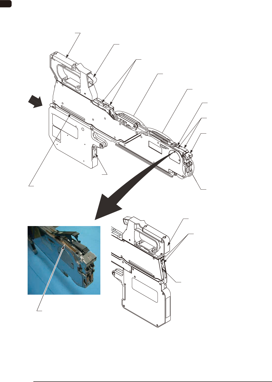
1.2 Name and Function of Each Section
It is described in GT-28080 (8 mm Dual Tape Feeder)
[8] Clamp Cancel Lever
[2] Tape Outlet Guide
[6] Cover Tape Tension Lever
[7] Cover Tape Take-up Release Lever
[1] Suppressor
[5] Chute
[3] Front Hook
[4] Sprocket
[12] Cover Tape Outlet Cover
[13] Cutter
[10] Connector
[9] Operation Panel
[11] Barcode Label
[15] Magnetic Plate Housing Section
[14] Magnetic Plate
View
View
FA3
0908-001

OM-1606
1. Scope
1-50908-001
[1] Suppressor
Feeding of the tape and releasing of the cover tape are performed smoothly
by pressing the cover tape against the chute.
During the operation, take care so that no foreign substance (chip component
or debris) is attached.
Two units are attached onto the dual tape feeder with 8 mm width.
A single unit is attached onto the dual tape feeder with 12 mm width or
more.
[2] Tape Outlet Guide
This guide discharges the tape.
This guide is attached only onto the dual tape feeder with 8 mm width.
[3] Front Hook
This hook holds the suppressor.
Two units are attached onto the dual tape feeder with 8 mm width.
A single unit is attached onto the dual tape feeder with 12 mm width or
more.
[4] Sprocket
This engages with the sprocket hole on the tape to feed the specied pitches
of the tape.
[5] Chute
This is the tape running surface close to pick-up position.
During the operation, take care so that no foreign substance (chip component
or debris) is attached.
Two units are attached onto the dual tape feeder with 8 mm width.
A single unit is attached onto the dual tape feeder with 12 mm width or
more.
[6] Cover Tape Tension Lever
Guides the released cover tape to the cover tape housing section.
[7] Cover Tape Tale-up Release Lever
This button is pressed when the cover tape is set to or taken from the cover
tape housing section.
Two units are attached onto the dual tape feeder with 8 mm width.
A single unit is attached onto the dual tape feeder with 12 mm width or
more.