OM-1606-006w_GT-28x.pdf - 第79页
OM-1606 4-1 4. Operation Panel 4. Operation Panel On the operation panel, the following displays and operations are available. • Display of the set pitch • I/O status display for the sensor, etc. • Display of the se…

OM-1606
3-8
3. Tape Feeder Attachment and Detachment Procedures
0908-001
OM-1606
4-1
4. Operation Panel
4. Operation Panel
On the operation panel, the following displays and operations are available.
•
Display of the set pitch
•
I/O status display for the sensor, etc.
•
Display of the selected lane
•
Subject Lane Selection
•
Tape Feeding
•
Feed Pitch Setting
•
Display of the error codes
•
Tape returning operation
•
Display of the splicing guide
•
Cover Tape Take-up Operation
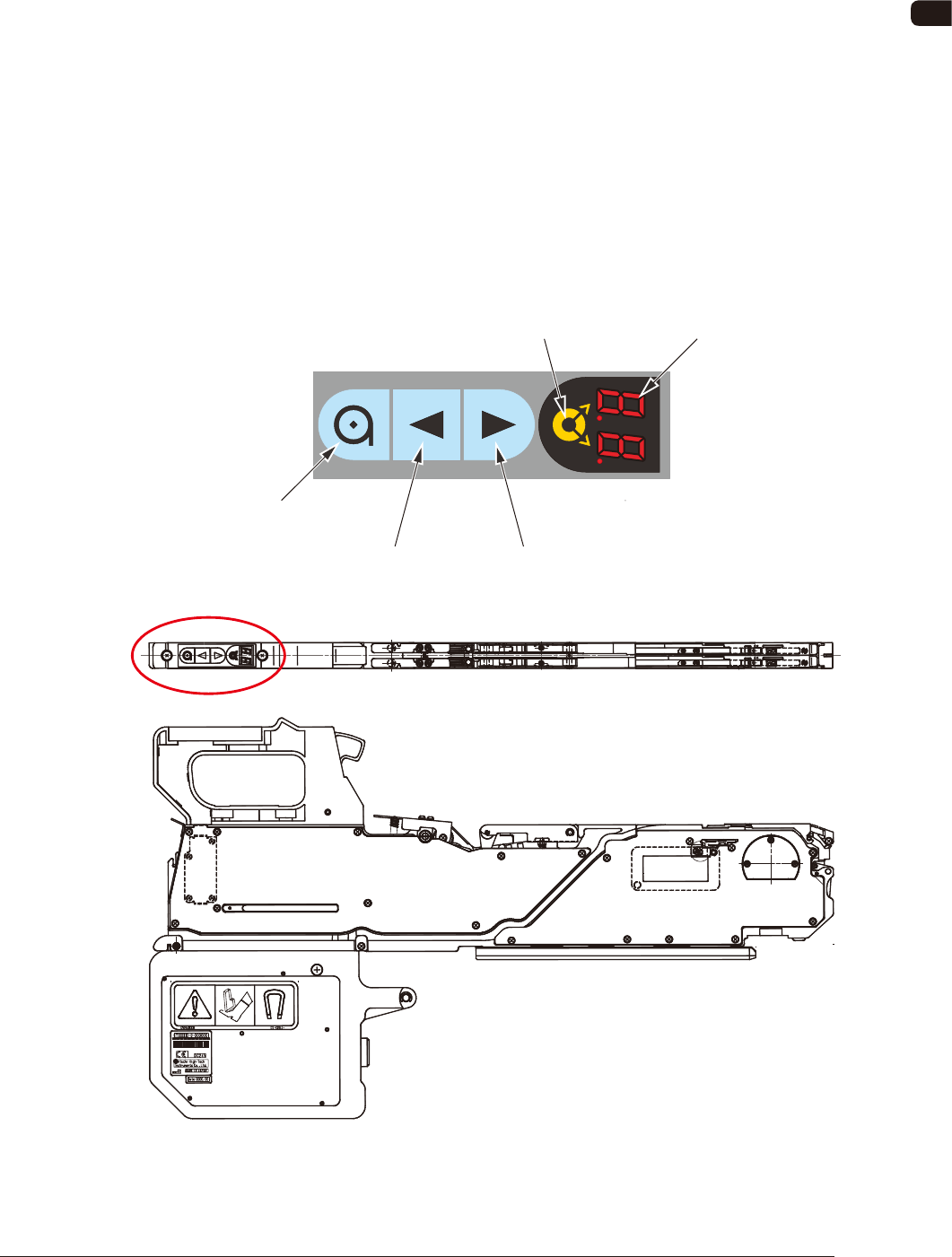
4.1 Name and Function of Each Section on Operation Panel
The tape feeder operation buttons and indicators are arranged integrally on the
operation panel.
Operation Panel
Digital IndicatorLane Selection Button
Forward ButtonBackward Button
Take-up Button
FD1
0908-001
OM-1606
4-2
4. Operation Panel
0908-001
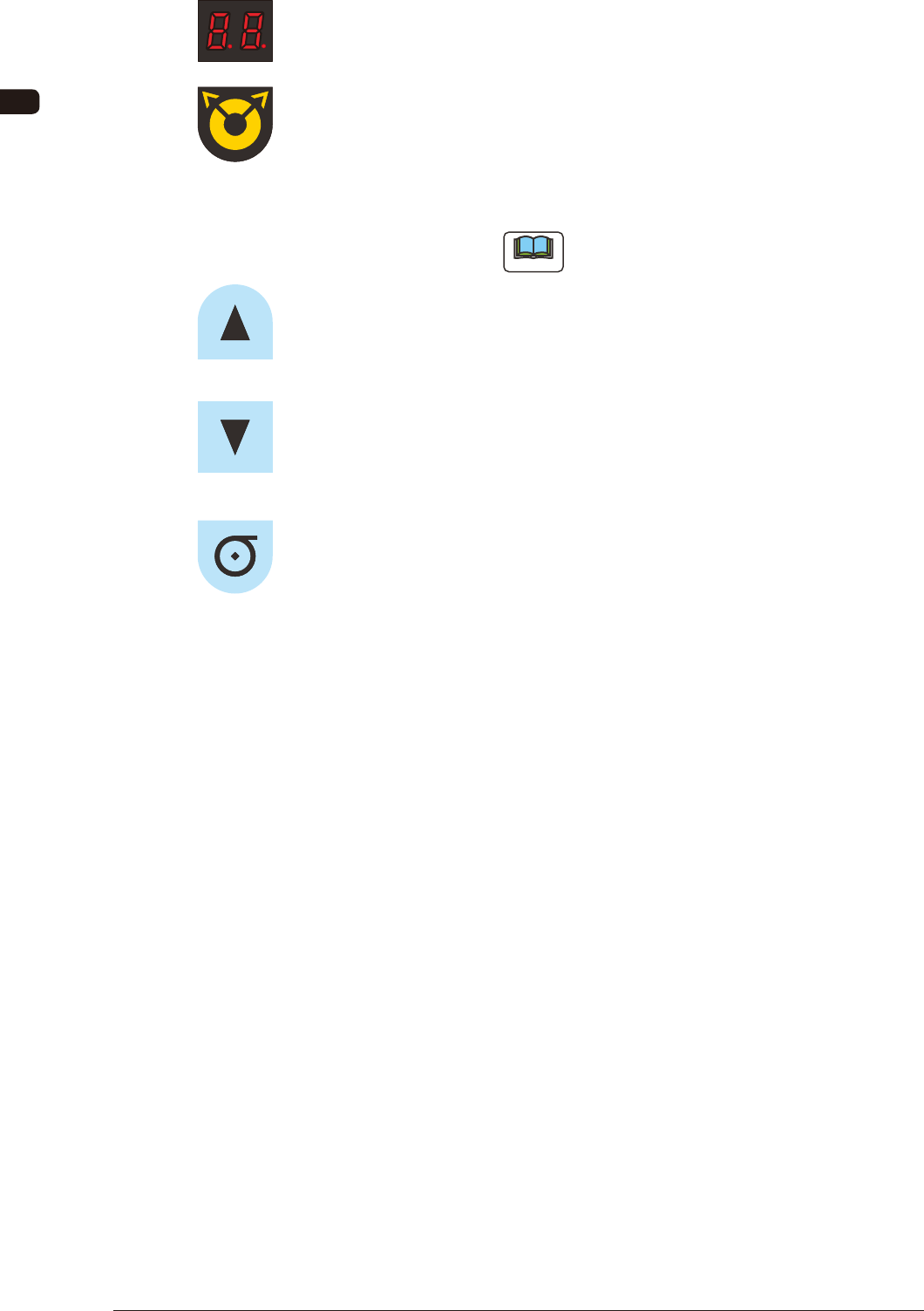
Digital Indicator
: Shows the set pitch, selected lane, error code or
splicing guide.
Lane Selection Button
: Used when the lane is selected.
Each pressing on this button changes the lane to the
left or right.
(Only for 8 mm width Tape Feeder)
Note
Use the return button together with it in the
tape returning operation.
Forward Button
: Used for tape feeding operation and feed pitch data
change.
Backward Button
: Used for tape returning operation and feed pitch
data change.
Take-up Button
: Used for taking up cover tape and as control key for
composite operations.