5OM-1011-002.pdf - 第100页
Section 5 Electrical Circuit Diagram Tg0861-PM-MD Operation Box A SDS IN 0305-001-(M805WBM--0002) 5-57 START (A) MOVE (A) ZERO (A) Reserved STOP (A) PAUSE (A) RESET (A) SYS CLR (A) Reserved PNL CHANGE (A) READY (A) Reser…
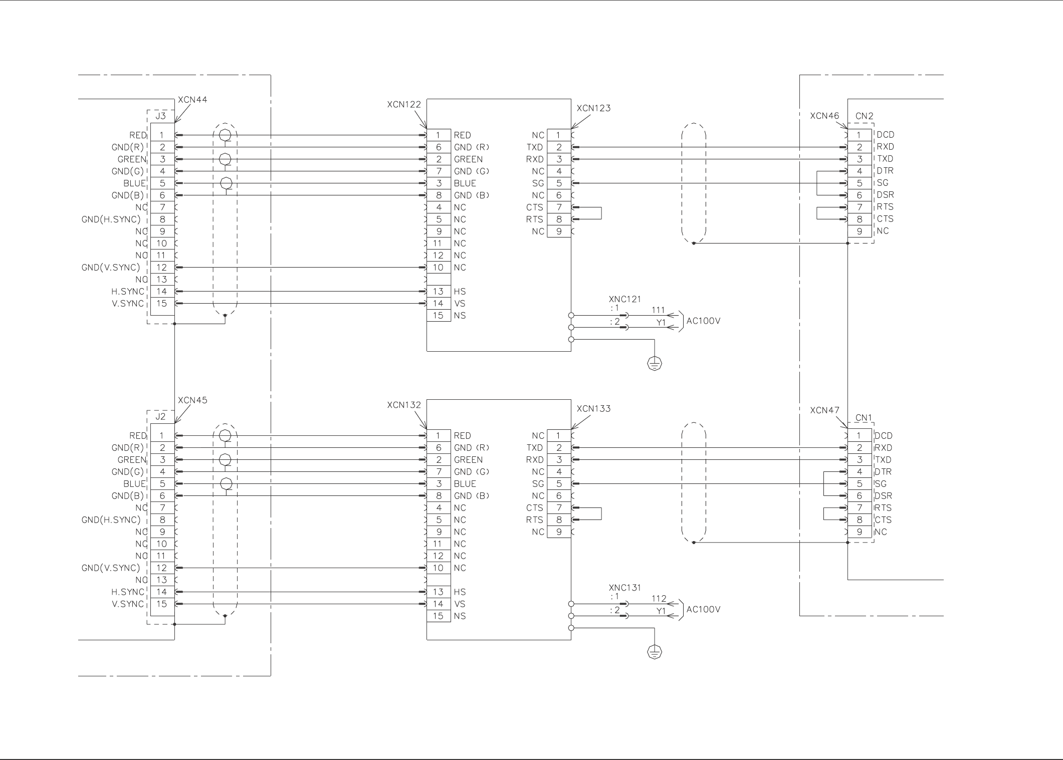
Section 5 Electrical Circuit Diagram
Tg0861-PM-MD
Front and Rear Operation Display Connection Diagram
0305-001-(M805WBM--0001) 5-56
Control Box
Control Box
Color Graphic
Board
BC Block
BC Block
Operation Box A LCD
Operation Box B LCD
Internal Setting of Board:
Modem Connection (Straight)
Internal Setting of Board:
Modem Connection (Straight)
Serial Port Module
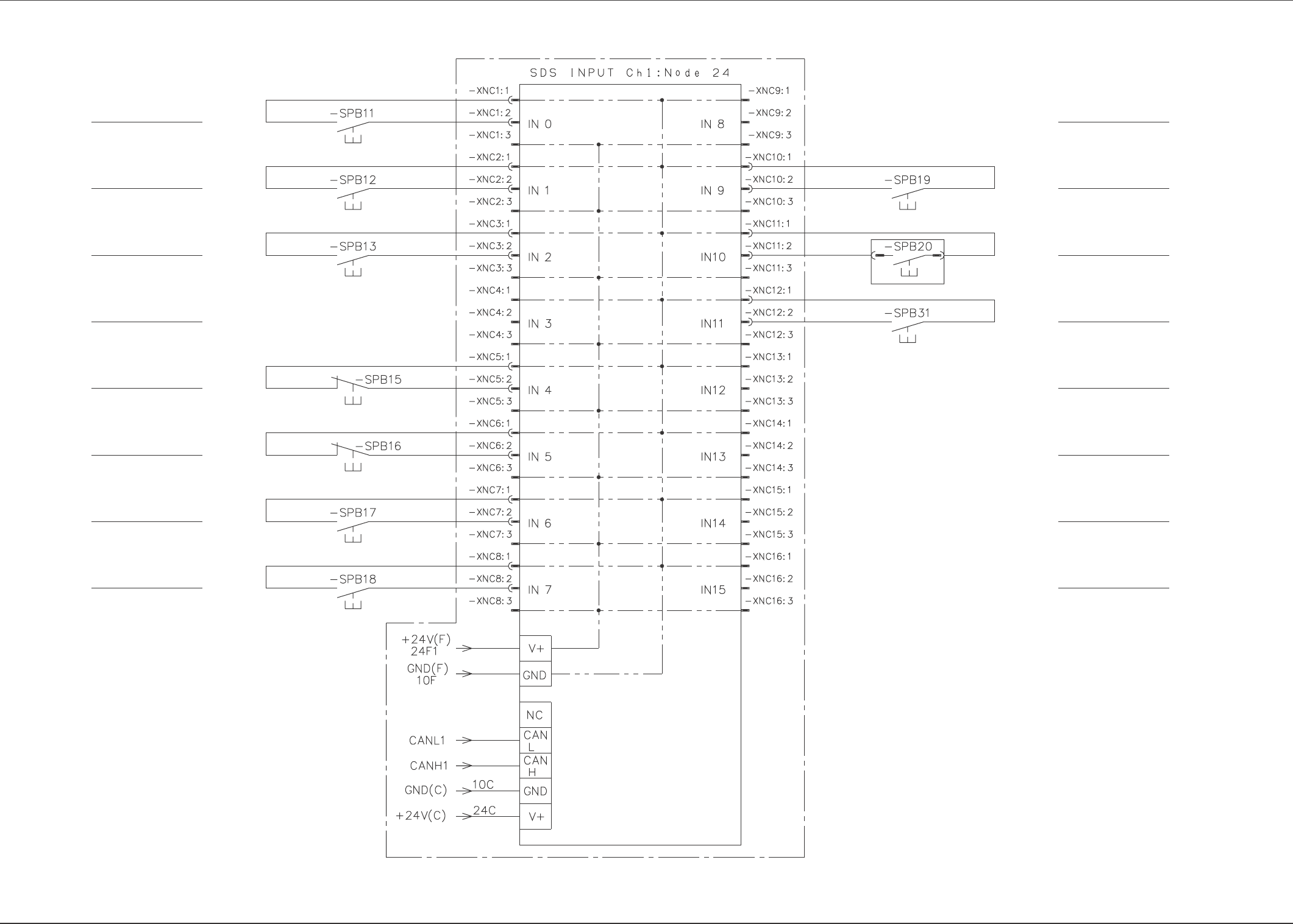
Section 5 Electrical Circuit Diagram
Tg0861-PM-MD
Operation Box A SDS IN
0305-001-(M805WBM--0002) 5-57
START (A)
MOVE (A)
ZERO (A)
Reserved
STOP (A)
PAUSE (A)
RESET (A)
SYS CLR (A)
Reserved
PNL CHANGE (A)
READY (A)
Reserved
Reserved
Reserved
BM (A) Block
BB Block
BM (A) Block
BL Block
Feeder Bank
Replacement Switch (A)
LED (OPTION)
CONSOLE CHANGE(A)
(OPTION)
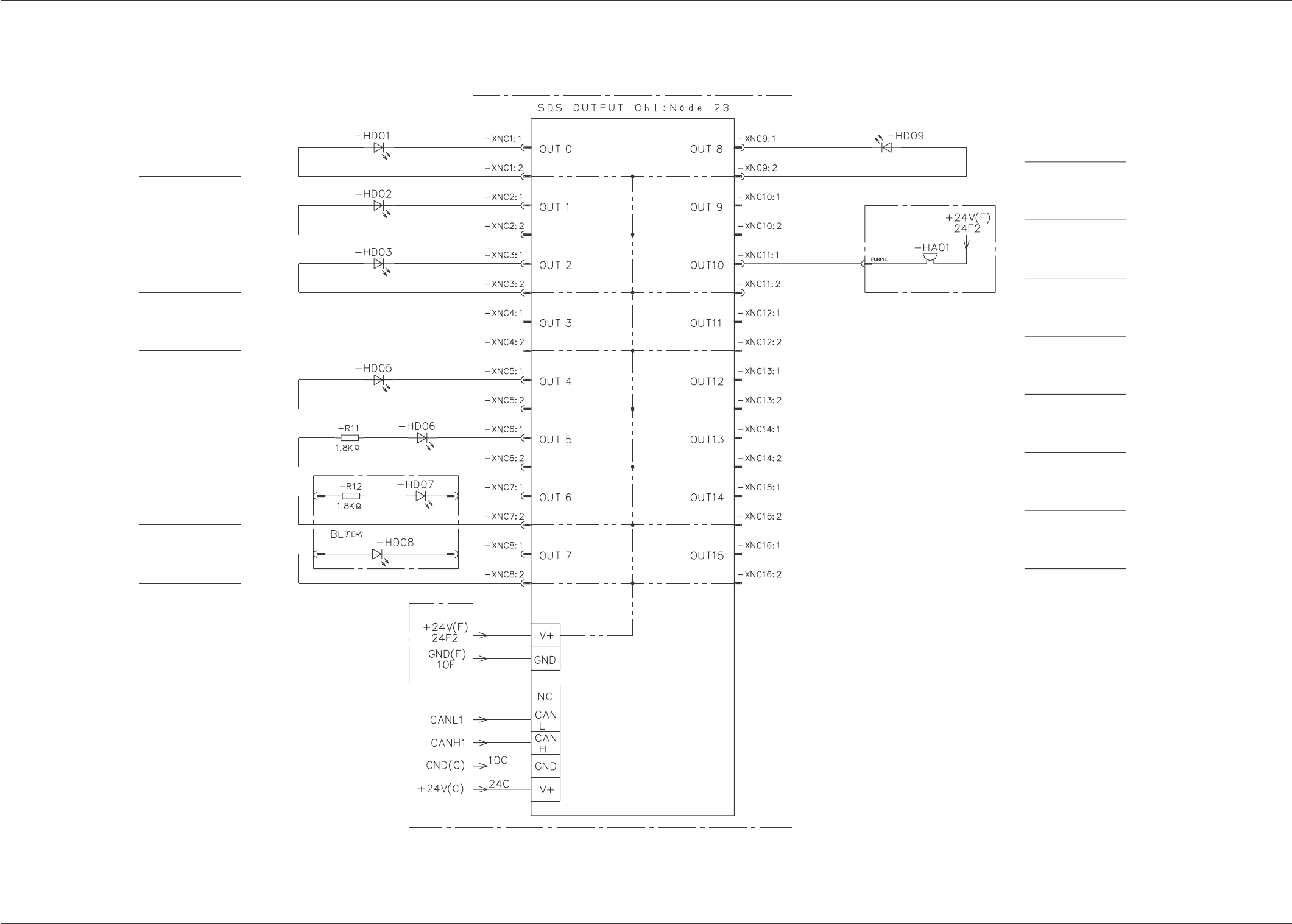
Section 5 Electrical Circuit Diagram
Tg0861-PM-MD
Operation Box A SDS OUT
0307-002A(M805WBM--0003) 5-58
*Included in the tower light assembly.
Light tower built-in buzzer.
START (A) LED
MOVE (A) LED
ZERO (A) LED
Reserved
PNL CHANGE (A) LED
LOCK (A) LED
CONSOLE CHANGE
(A) LED (OPTION)
CONSOLE LOCK
(A) LED (OPTION)
BM (A) Blcok
BB Blcok
BM (A) Blcok
READY (A) LED
BUZZER (A)
Reserved
Reserved
Reserved
Reserved
Reserved
Feeder Bank Replacement
Switch (A) LED (Option)