5OM-1011-002.pdf - 第126页
Section 5 Electrical Circuit Diagram Tg0861-PM-MD T ray Connection Section 0305-001-(M805WTT--0006) 5-83 Power Supply for Tray Feeder Emergency Stop Refer to the safety circuit Emergency Stop Refer to the safety circuit …
Section 5 Electrical Circuit Diagram
Tg0861-PM-MD
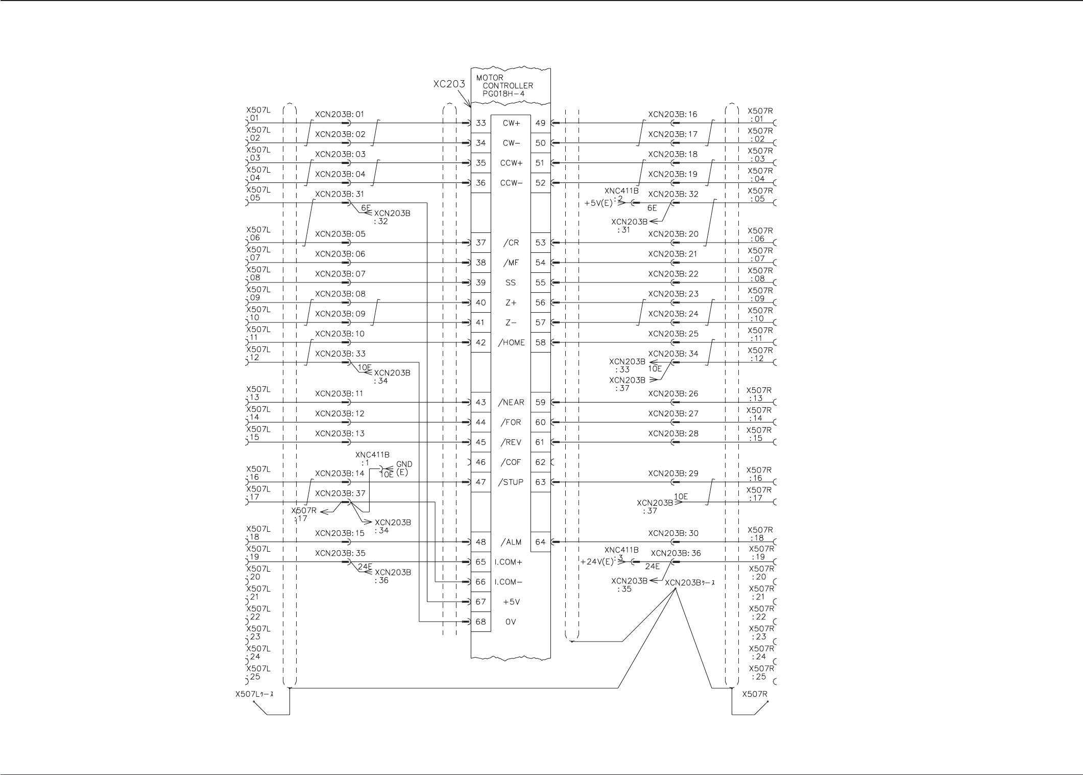
Tray Control Board 5-2
0305-001-(M805WTT--0003) 5-82
C Axis
D Axis
Case
Section 5 Electrical Circuit Diagram
Tg0861-PM-MD
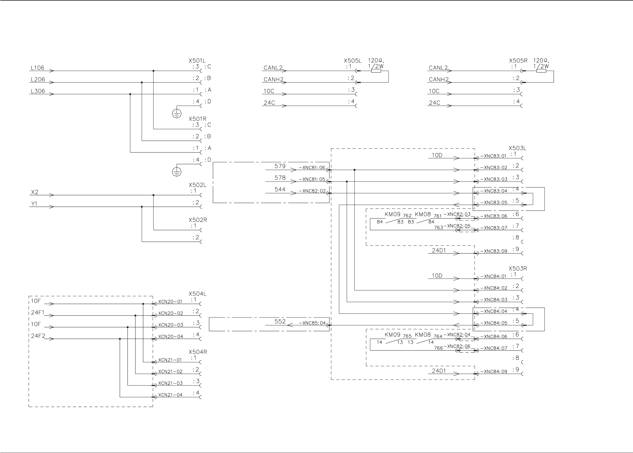
Tray Connection Section
0305-001-(M805WTT--0006) 5-83
Power Supply for Tray Feeder
Emergency Stop
Refer to the safety circuit
Emergency Stop
Refer to the safety circuit
Emergency Stop
Refer to the safety circuit
(From K99)
(From K99)
(From the KM09
suxiliary contacts)
(To the KM31 auxil-
iary contacts)
To Tray Feeder L (Option)
To Tray Feeder R (Option)
Note:
The areas surrounder by the dashed line belong to the relay P.C.B. (UA18 & UA19).
Emergency Stop
Refer to the safety circuit
Section 5 Electrical Circuit Diagram
Tg0861-PM-MD
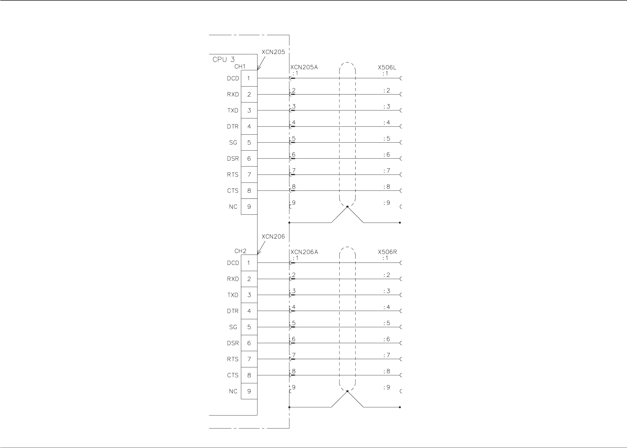
Tray RS-232C Connection
0305-001-(M805WTT--0007) 5-84
Control Box
XCN205A
Case
X506L Case
XCN206A
Case
X506R Case
BC Block