5OM-1011-002.pdf - 第74页
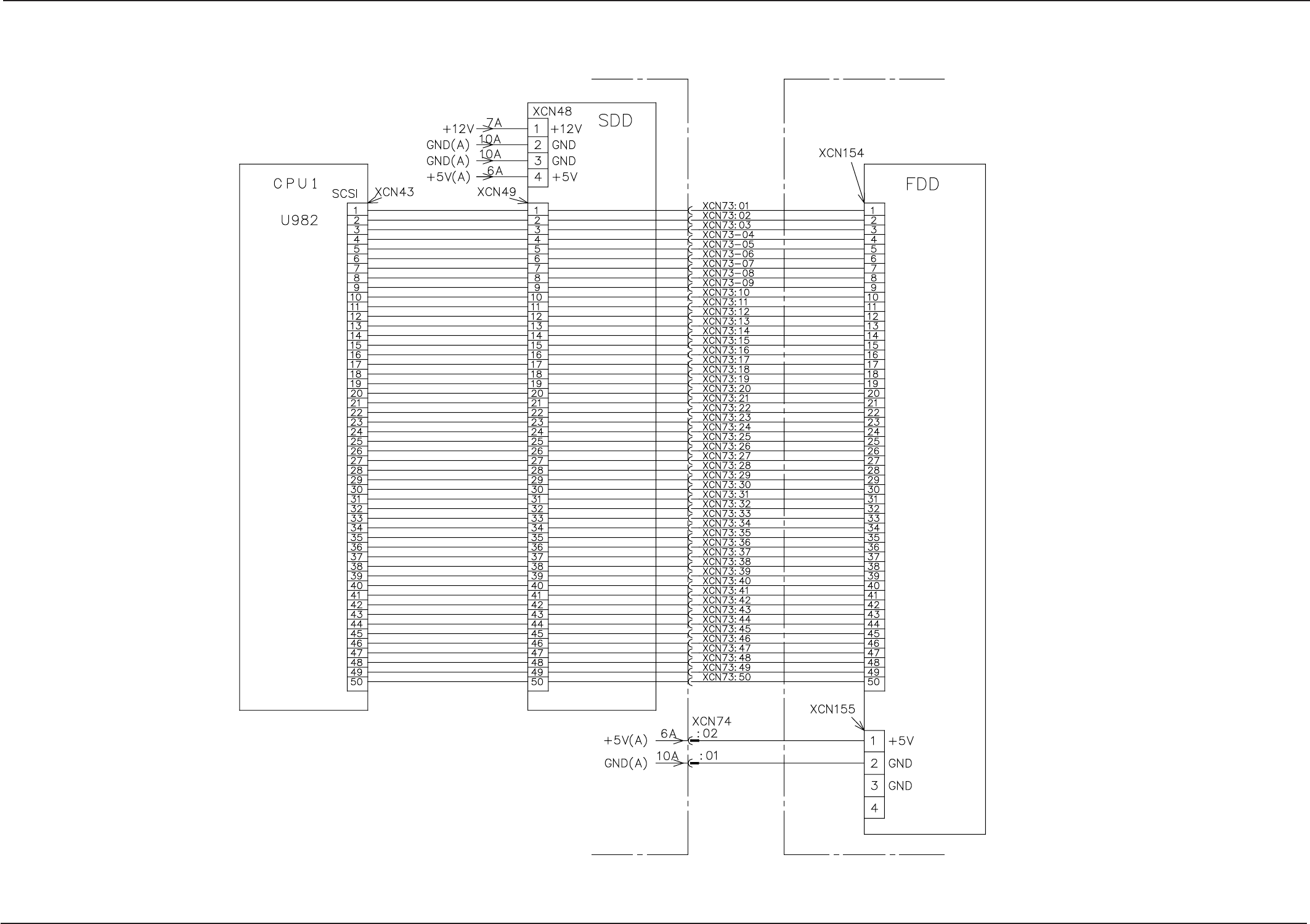
Section5 Electrical Circuit Diagram 0305-001- (M805WBC--0002) 5-31 Tg0861-PM-MD HDD/FDD Circuit Inside of Control Box Inside of Conveyor 1 Box BK Block Board

Section5 Electrical Circuit Diagram
0305-001- (M805WBC--0001) 5-30 Tg0861-PM-MD
Control Box Power Supply Circuit
SDS Silicon Disk
Power Supply 1
To each
external
SDS node
Relay Connector Board
To the DI/O
board
To Power
Supply
Section 2
To each
external
SDS node
To the SDS
node in the
control box
Module CH0
Module CH1
To the external
FDD power supply
connector
To the HDD
power supply 2
connector
Option
Section5 Electrical Circuit Diagram
0305-001- (M805WBC--0002) 5-31 Tg0861-PM-MD
HDD/FDD Circuit
Inside of Control Box Inside of Conveyor 1 Box
BK Block
Board
Section5 Electrical Circuit Diagram
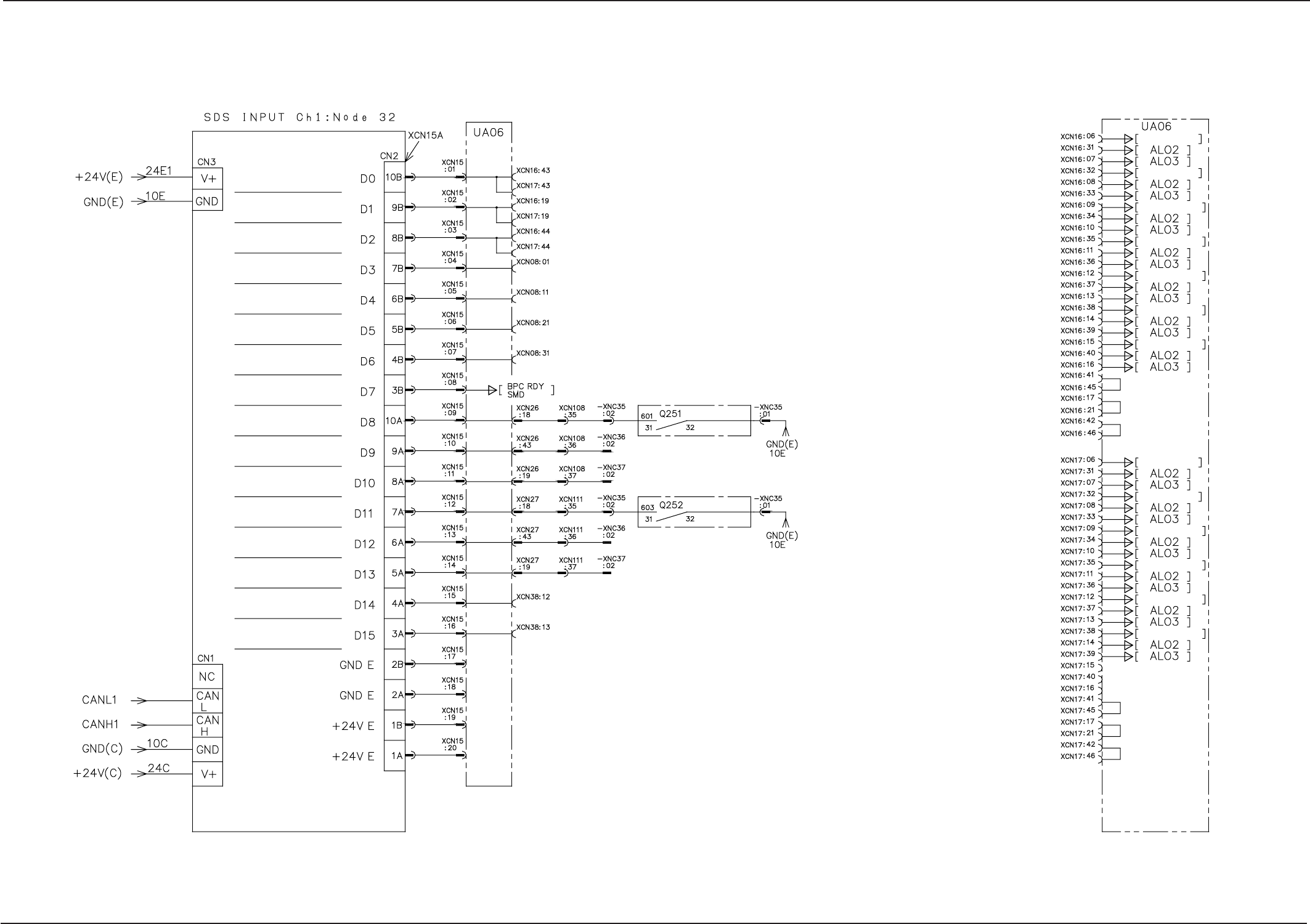
0305-001- (M805WBC--0003) 5-32 Tg0861-PM-MD
C-BOX SDS IN Board 1
Servo Alarm Code 1
Servo Alarm Code 2
Servo Alarm Code 3
ZA1-Axis Ready
ZA2-Axis Ready
ZB1-Axis Ready
ZB2-Axis Ready
BPC-Axis Ready
Feeder (A)
Circuit Breaker OFF
Feeder (B)
Circuit Breaker OFF
Reserved
Reserved
Reserved
Reserved
Reserved
Reserved
Relay Connector Board
Relay Connector Board
BJ Block
BJ Block
XA Axis AL01
YA Axis AL01
LA1 Axis AL01
LA2 Axis AL01
ZA1 Axis AL01
ZA2 Axis AL01
BPC Axis AL01
XB Axis AL01
YB Axis AL01
LB1 Axis AL01
LB2 Axis AL01
ZB1 Axis AL01
ZB2 Axis AL01