5OM-1011-002.pdf - 第49页
Section5 Electrical Circuit Diagram Power Supply Circuit Diagram (1) 0305-001A(M805WB---0001) 5-6 Tg0861-PM-MD Power Supply for V accum Pump Motor BB Block Axis Axis Main Circuit Power Supply Axis Axis Axis Main Circuit …
Section5 Electrical Circuit Diagram
2. Electrical Circuit Diagram
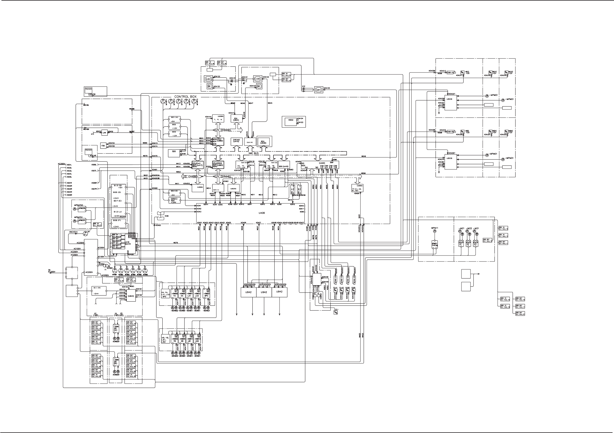
General Block Connection Diagram
0305-001A(M805WA---0001) 5-5 Tg0861-PM-MD
BM (A) Block
Operation
Switch
BM (B) Block
Operation
Switch
4-Axis
Motor Controller
Mechanical
Distribution Board (2)
Mechanical
Distribution Board (3)
Mechanical
Distribution Board (4)
A Beam Servo
B Beam Servo
Main Body (D, F, G,
N, P) Base
MB (A)
Block
CB (A) Block
MC (A)
Block
Head Sensor
Head Lighting A
(Right)
Head Lighting A
(Left)
P.E.C. Recognition
Lighting
Mechanical Distribution Board (2)
P.E.C. RECOG.
Camera A
Head Sensor
A Head
MB (B)
Block
CB (B) Block
MC (B)
Block
Head Lighting B
(Left)
Head Lighting B
(Right)
Mechanical Distribution Board (3)
B Head
Head Sensor
Head Sensor
P.E.C. Recognition
Lighting
P.E.C. RECOG.
Camera B
Recognition Monitor
Operation Monitor
Option
Option
Serial
Display (CRT)
Operation Monitor
Serial
4-Axis
Motor Controller
Recognition Board
Serial I/O
Controller
4-Axis
Motor Controller
ZA1 Axis
ZA2 Axis
ZB1 Axis
ZB2 Axis
(Track
Ball)
BB Block
Conveyor Width
Conveyor
Control
BL Block
(Conveyor 2)
BK Block
(Conveyor 1)
P.C.B. Detection
P.C.B. Detection
P.C.B. Positioning
Stopper
Conponent Detection
Conponent Detection
YA-Axis Stopper
YB-Axis Stopper
Light Tower
Mechanical Distribution
Board (4)
Lifted Feeder
Detection
Sensor
Lifted Nozzle
Detection
Sensor
Offset Lighting
BL Block
LED
Lighting
Control
Board
CMPNT RECOG LTG A CMPNT RECOG CAMR A (Left)
CMPNT RECOG LTG B CMPNT RECOG CAMR B (Left)
CMPNT RECOG LTG A CMPNT RECOG CAMR A (Right)
CMPNT RECOG LTG B CMPNT RECOG CAMR B (Right)
4-Axis
Motor Controller
Relay Connecter Board
I/O Board
Interlock
Board
4-Axis
Motor Control
For Pulse
For CPU
For CPU
For CPU
Option
(Track Ball)
BB Block
BL Block (Rear Side)
BL Block (Front Side)
Operation Monitor Signal
Operation Monitor Signal
Tray Feeder R
Tray Feeder L
Power Supply
Section 2
Traverse 1 Axis
Traverse 2 Axis
Vaccum Pump
Motor
BG Block
TT Block
Power Supply Section 2
BH Block
Relay P.C.B.
For Head Motor
For Operation
Relay Circuit
For SDS Node,
Feeder,
and Lighting
BG Block
For
Communication
For I/O around
mechanical distribution
Main Body, Air Pressure, YA, B-Axis
Stationar Position Stopper, Cover
Solenoid Lock, Sensor
A Beam, YA, XA, LA1 Axis, LA2 Axis
Position, Interlock, Sensor
B Beam, YB, XB, LB1 Axis, LB2 Axis
Position, Interlock, Sensor
Lifted Tape Feeder, Nozzle Stocker
P.C.B. DetectionBPC,
PWC, PPC Axis Position, Sensor
UC Block
(Inside the Power Supply 4 Box)
Power
Supply
Section 1
BF Block
Power
Supply
Section 4
BJ Block
BJ Block
Input/Output
I/F Board
For Input/Output
I/F Board
Furnace
Signal
Output
Machines I/F
Intput
Machines I/F
QG (A) Block
QG (B) Block QG (B) Block
QG (A) Block
TF (B1) Axis
TF (A1) Axis
Servo Power
Supply Section
Servo Power
Supply Section
BE Block
Backup Base
Axis
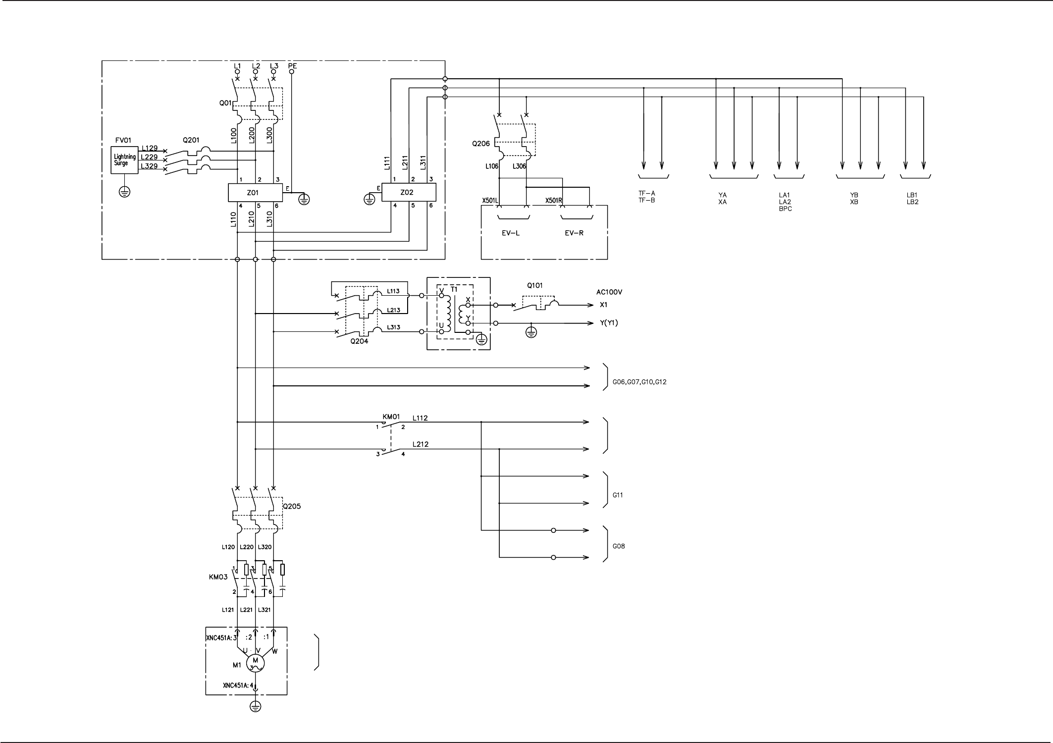
Section5 Electrical Circuit Diagram
Power Supply Circuit Diagram (1)
0305-001A(M805WB---0001) 5-6 Tg0861-PM-MD
Power Supply for
Vaccum Pump Motor
BB Block
Axis
Axis
Main Circuit Power Supply
Axis
Axis
Axis
Main Circuit Power Supply
Axis
Axis
Main Circuit Power SupplyMain Circuit Power Supply Main Circuit Power Supply
Axis
Axis
Servomotor Driver
Control Circuit
Multi-Power Unit
For Input/Output Machine I/F
For I/O
Main Circuit Power Supply Main Circuit Power Supply
BF Block
BB Block
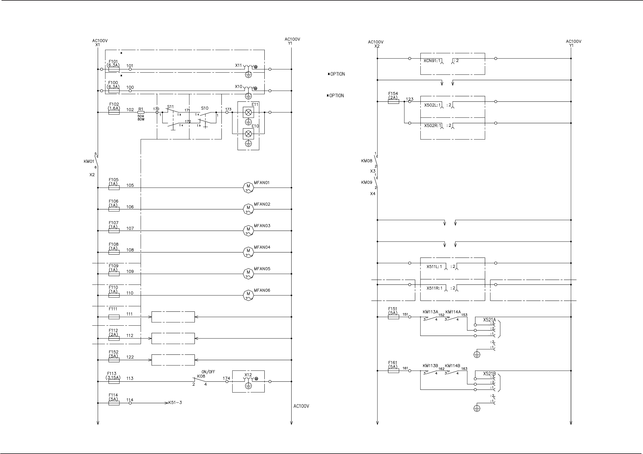
Section5 Electrical Circuit Diagram
Power Supply Circuit Diagram (2)
0305-001- (M805WB---0002) 5-7 Tg0861-PM-MD
BK Block
BL Block
BK Block
BL Block
BB Block
Lighting
Lighting
Power Supply for Programming Device
(Console Power Supply)
Plane B (Front Side)
Power Supply for Programming Device
(Console Power Supply)
Plane A (Rear Side)
Lighting for Servicing
Plane B (Front Side)
Lighting for Servicing
Plane A (Rear Side)
For Exhaustion Cooling Fan
(Front Left)
For Exhaustion Cooling Fan
(Front Right)
For Exhaustion Cooling Fan
(Front Side)
For Exhaustion Cooling Fan
(Back Side)
Control Box Section
For DC Power Supply
To Traverse Axis Motor Driver
To Multi-Layer Tray L
To Multi-Layer Tray R
Operation Box A
Connecter for Monitor
Operation Box B
Connecter for Monitor
Recognition Monitor
Power Supply
for Loads
To Extended EL Conveyor (Option)
Transfer Motor
To Extended ER Conveyor (Option)
Transfer Motor
To Component Dischange Conveyor A (Option)
Transfer Motor
To Component Dischange Conveyor B (Option)
Transfer Motor
BK Block
BK Block
Control Power Supply
Power Outlet
for Recognition Monitor
Plane B (Front Side)
Safety Relay
BG Block
BL Block
BK Block
BL Block
BK Block
The wiring after the block BK shall be optional.
The wiring after the block BL shall be optional.
LA1, 2, LB1, 2, BPC
Servo-Brake Power Source
Lower Frame
Cooling Fan
(Right from the Center)
To PWC Axis Pulse Motor Driver
To Conveyor Motor