5OM-1011-002.pdf - 第78页
Section5 Electrical Circuit Diagram 0305-001- (M805WBC--0006) 5-35 Tg0861-PM-MD Recognition-Related Block Diagram Interlock Board Connector for Debugging BB Block T rack Ball (Beam B Side) Beam A Side Connector for T rac…
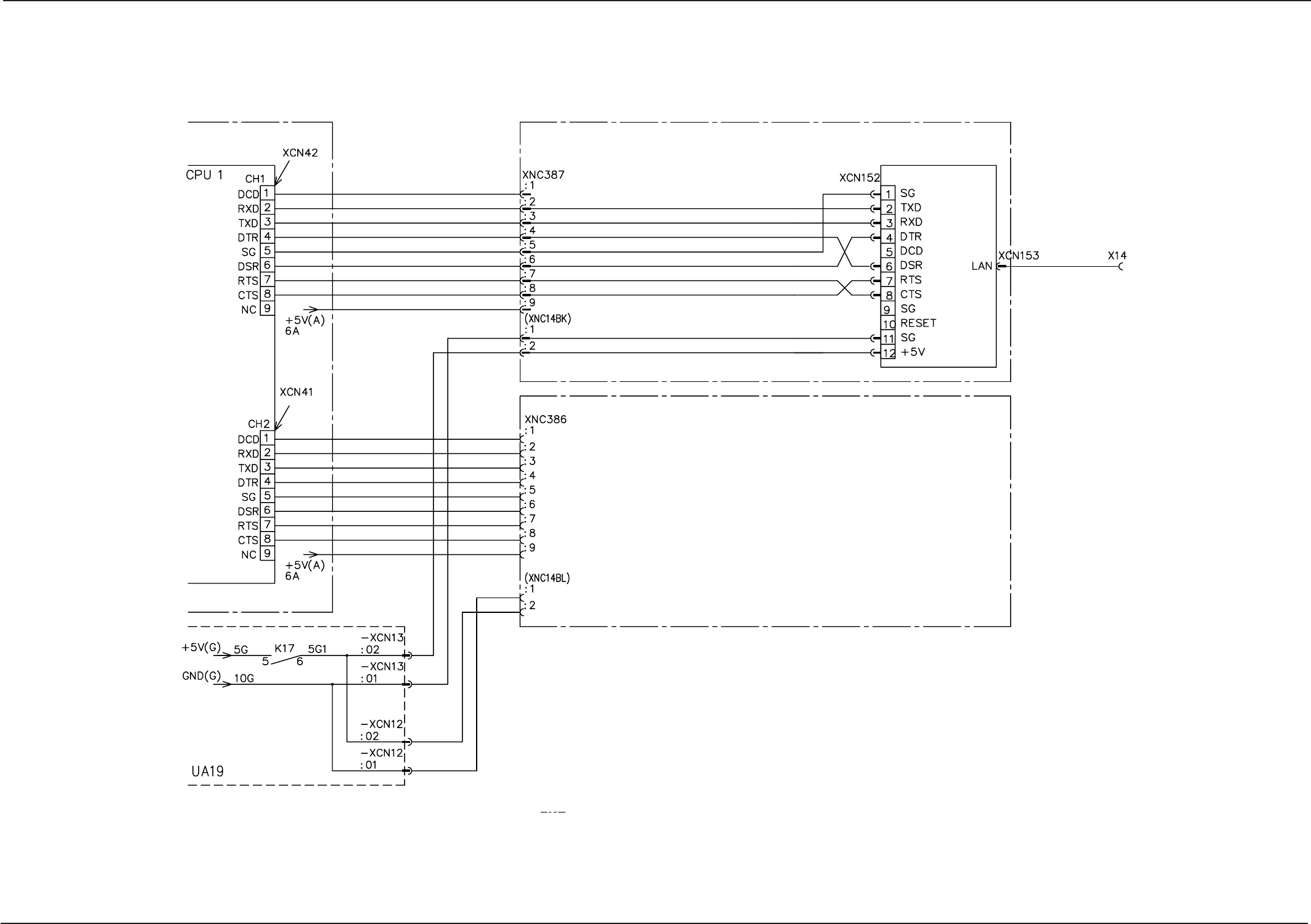
Section5 Electrical Circuit Diagram
0305-001A(M805WBC--0005) 5-34 Tg0861-PM-MD
RS-232C Connection Diagram
Control Box
LAN Board
Note: (a) The area surrounded by " " belongs to the relay P.C.B. (UA18 & UA19).
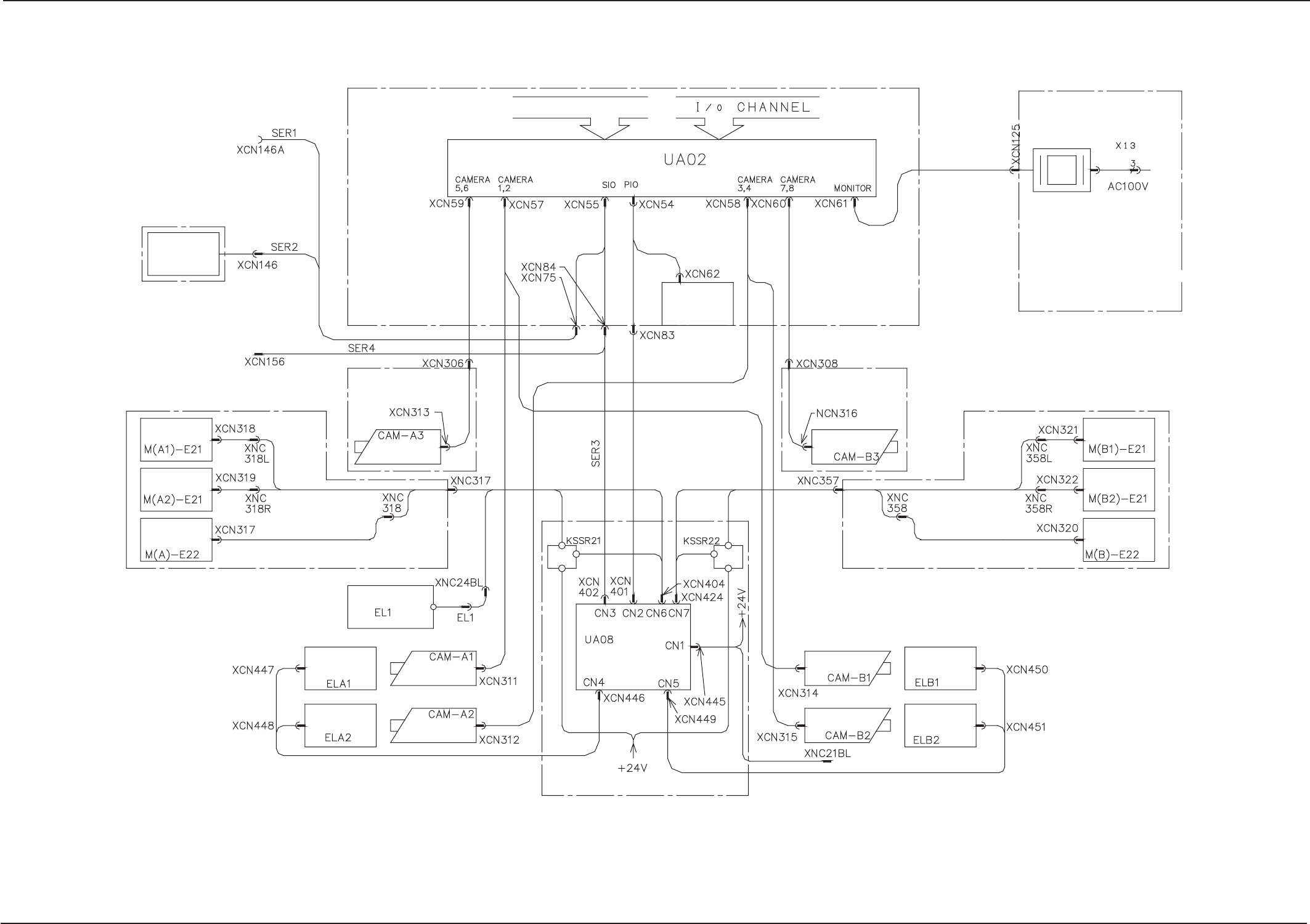
Section5 Electrical Circuit Diagram
0305-001- (M805WBC--0006) 5-35 Tg0861-PM-MD
Recognition-Related Block Diagram
Interlock Board
Connector for Debugging
BB Block
Track Ball
(Beam B Side)
Beam A Side
Connector for
Track Ball
Beam A
Beam A
Control Box
Head Lighting A
(Left)
Head Lighting A
(Right)
Beam A
P.E.C. Recognition
Lighting
A Beam P.E.C.
Recognition Camera
Offset Lighting
Fixed Chute Side
Component
Recognition
Lighting A (Left)
Component
Recognition
Camera A (Left)
Component
Recognition
Camera A (Right)
Component
Recognition
Lighting A (Right)
VME BUS
Recognition Board
LED Light Control Board
Conveyor 2 Box
BL Block
Beam B
Component Recognition
Camera B (Right)
Component Recognition
Camera B (Left)
Component
Recognition
Lighting B (Right)
Component
Recognition
Lighting B (Left)
Beam B
Beam B P.E.C.
Recognition Camera
Head Lighting B
(Right)
Head Lighting B
(Left)
Beam B
P.E.C. Recognition
Lighting
BB Block
Recognition Monitor
(A Side)
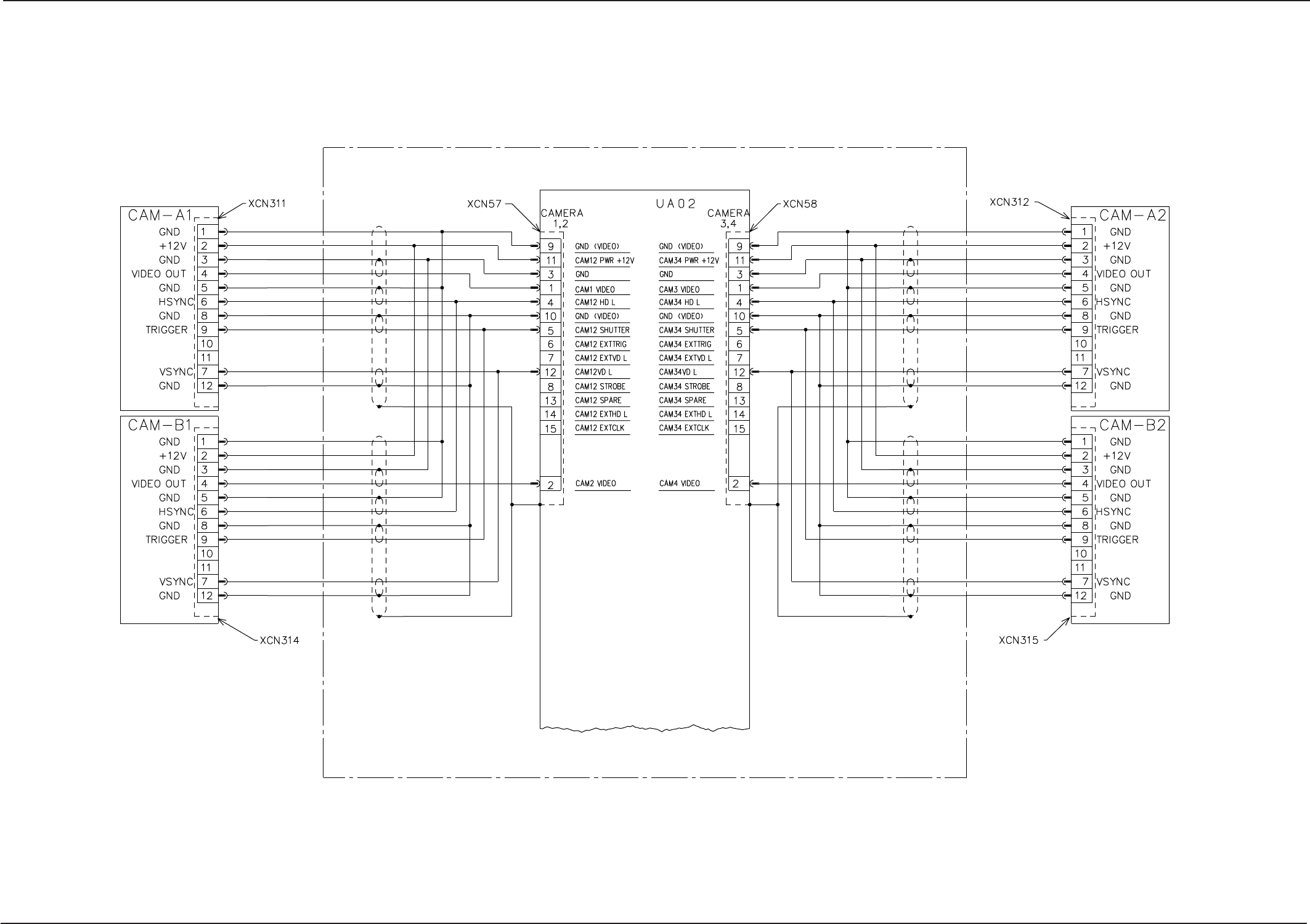
Section5 Electrical Circuit Diagram
0305-001- (M805WBC--0007) 5-36 Tg0861-PM-MD
COGNEX 4600 Connection Diagram 1
Control Box
Recognition Board
Component
Recognition Camera
A (Left)
Component
Recognition Camera
B (Right)
Shielded
Shielded
Component
Recognition Camera
A (Right)
Component
Recognition Camera
B (Left)
Shielded
Shielded