5OM-1011-002.pdf - 第130页
Section 6 Location of Sensors and Loads 0305-001 6- A Tg0861-PM-MD This section includes the sensor and load arrangement dia- gram for each section of the machine. Because highly spe- cialized descriptions are included, …
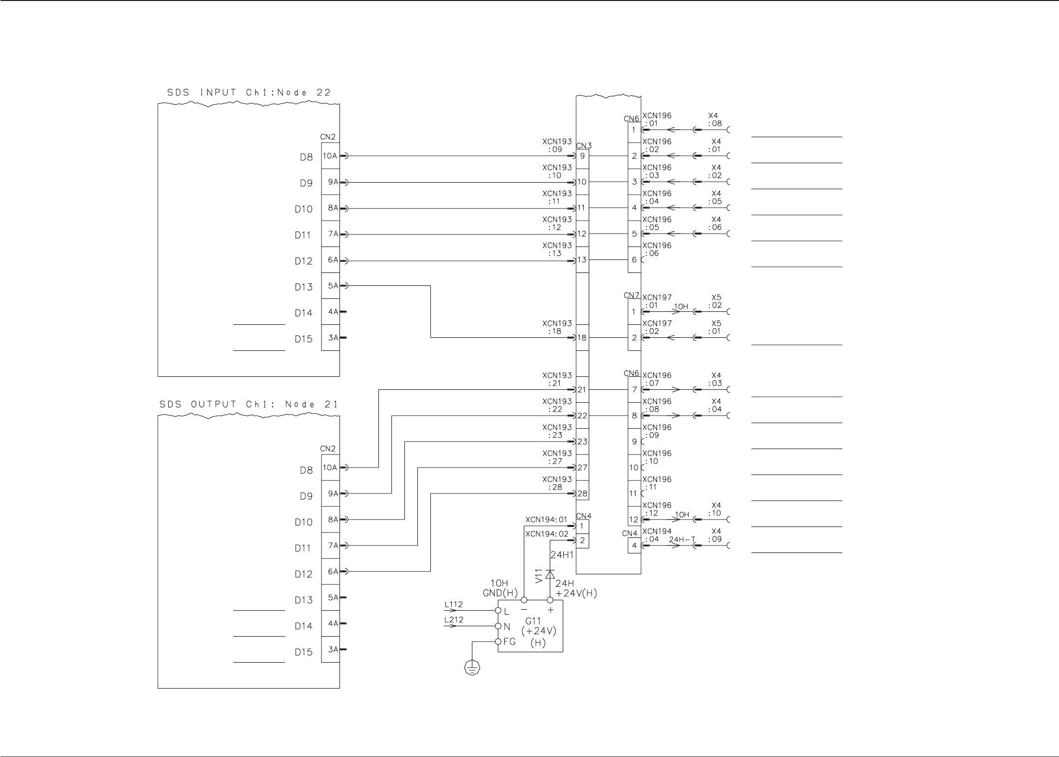
Section 5 Electrical Circuit Diagram
Tg0861-PM-MD
Input/Output Machine I/F Board (Output Machine)
0305-001-(M805WUC--0002) 5-86
Reserved
Reserved
Reserved
Reserved
Reserved
Power Supply 4 Box (BJ Block)
Input/Output Machine I/F Board
VCC for Input Machine Interface
(Supplied From the input machine)
Output Machine Run
Output Machine
P.C.B. Requiring
Output Machine Ready
Output Machine P.C.B.
Existene
Reserved Output
Machine Input
Furnace Signal
Run Singnal to Output
Machine
P.C.B. Transfer Signal to
Output Machine
Reserved Output 1 to
Output Machine
Reserved Output 2 to
Output Machine
Reserved Output 3 to
Output Machine
Main Machine GND
(To Output Machine)
Main Machine +24V
(To Output Machine)

Section 6
Location of Sensors and Loads
0305-001 6-A Tg0861-PM-MD
This section includes the sensor and load arrangement dia-
gram for each section of the machine. Because highly spe-
cialized descriptions are included, pay special care when
referring to them.

0305-001 6-B Tg0861-PM-MD