5OM-1011-002.pdf - 第25页
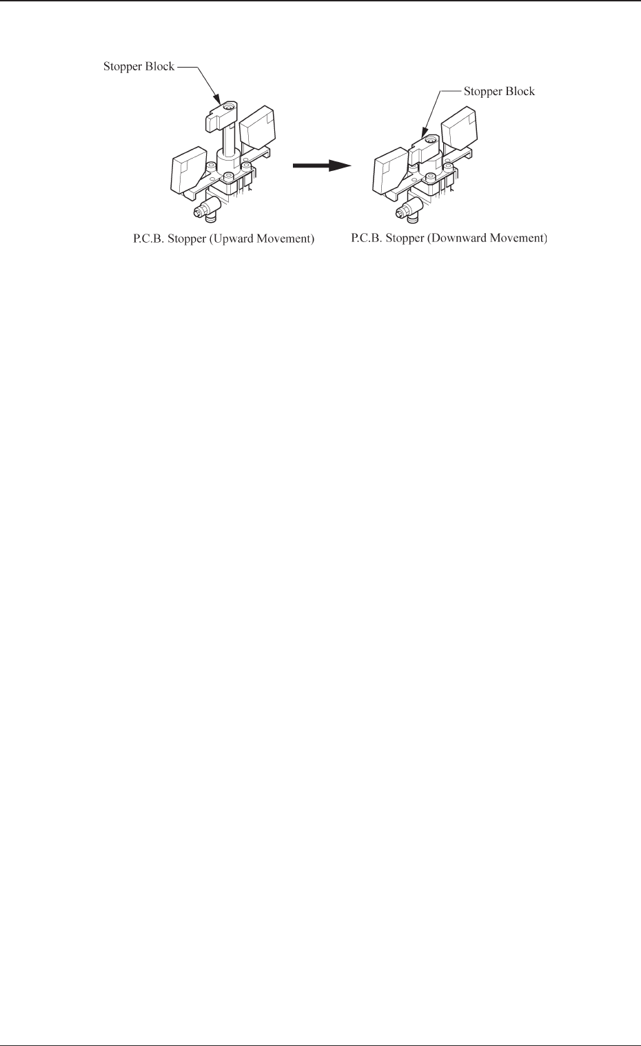
Tg0861-PM-MD (5) T urn on the power and move down the P .C.B. stopper . 0305-001 2-2 1. Adjustment of P .C.B. Positioning Section Fig. 5B3
Tg0861-PM-MD
1. Adjustment of P.C.B. Positioning Section
• The direction of the P.C.B. stopper block is adjusted in compliance with the
setting upon shipment of the machine.
When setting is changed, it is required to change the direction of the P.C.B.
stopper block according to the changed setting.
• See the figures depicted in “6.3 P.C.B. Transfer in Volume 1” for the direc-
tion of the P.C.B. stopper block.
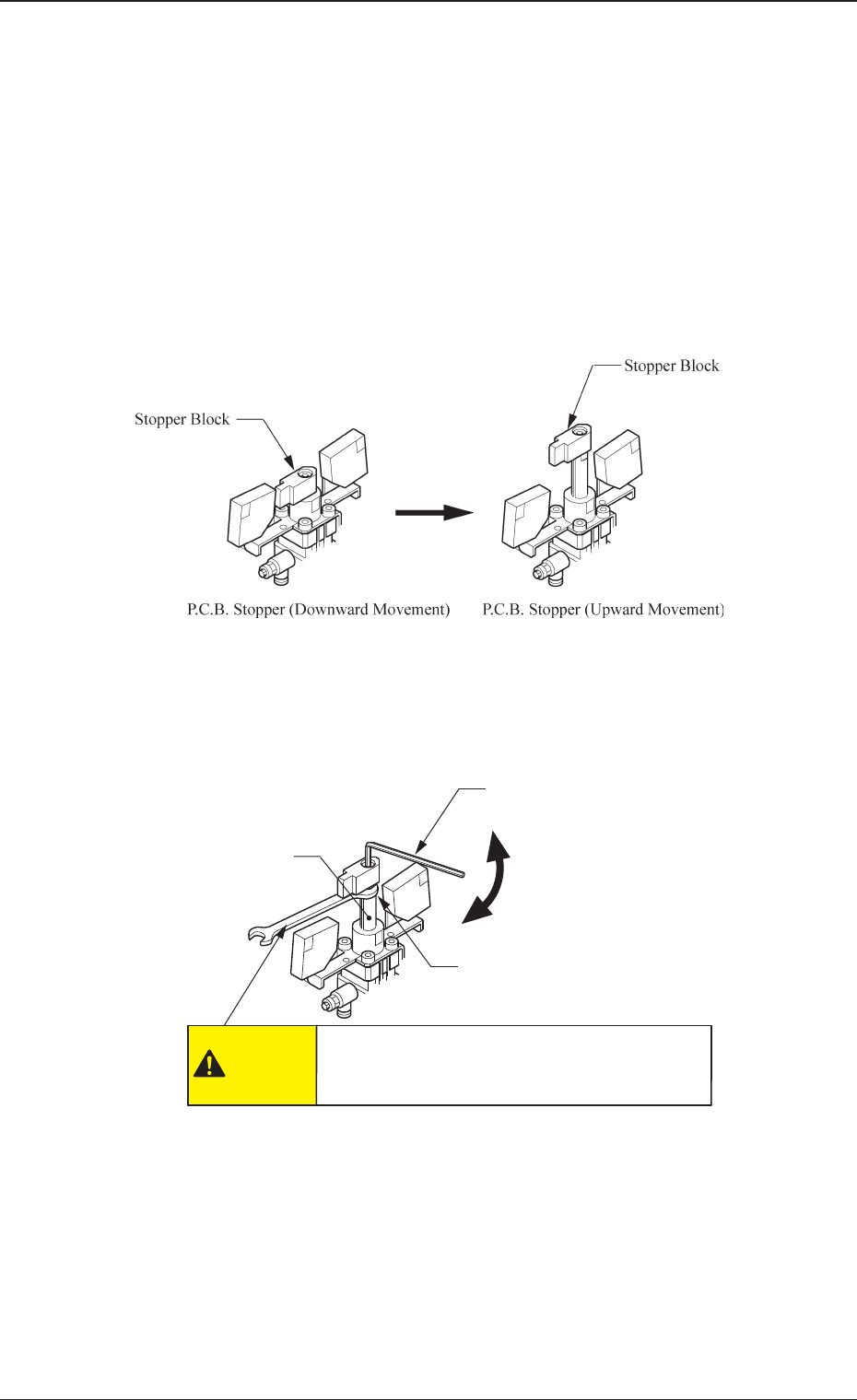
Procedure for Direction Change of Stopper Block
(1) Move up the P.C.B. stopper and shut off the power supply.
(2) Hold the cylinder rod with a wrench and remove the bolt fastening the
stopper block.
(3) Change the direction of the stopper block by 180° and insert it into the
cylinder rod.
(4) Hold the cylinder rod with a wrench and tighten the bolt fastening the
stopper block.
1. Adjustment of P.C.B. Positioning Section
0305-001 2-1
Wrench (10 mm)
Hexagon Wrench (for M5)
Cylinder Rod
Tighten
Loosen
CAUTION
Hold the cylinder rod with a wrench such that
the cylinder rod does not rotate.
Otherwise, the P.C.B. stopper may be broken.
Fig. 5B1
Fig. 5B2
Tg0861-PM-MD
(5) Turn on the power and move down the P.C.B. stopper.
0305-001 2-2
1. Adjustment of P.C.B. Positioning Section
Fig. 5B3

Section 3
Convenient Function
0305-001 3-A Tg0861-PM-MD
This section explains such convenient functions as the auto-
matic operation substitution display and the machine informa-
tion display, etc.