5OM-1011-002.pdf - 第52页
Section5 Electrical Circuit Diagram Emergency Stop Safety Relay Circuit 0305-001- (M805WB---0004) 5-9 Tg0861-PM-MD T ray T ray G Block Maintenance Cover A Detection Maintenance Cover B Detection LB1-Axis Main Circuit Pow…
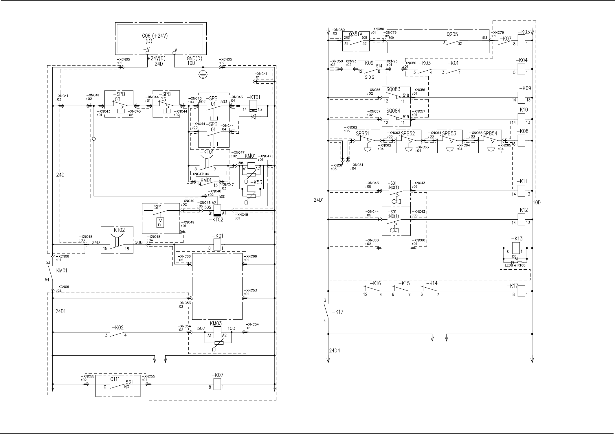
Section 5 Electrical Circuit Diagram
Power Supply Circuit Diagram (3)
0307-002A(M805WB---0003) 5-8 Tg0861-PM-MD
SLOT 2
Note:
The areas surrounded by the dashed line belong to the relay P.C.B. (UA18 & UA19)
PWC Axis
Vacuum Pump
BPC Axis
BD Block
BC Block
24V Check
G Block
Power Supply
for Loads
Emergency Stop
Safety Relay(K99)
CB OFF
BG Block
Multi-Power Unit
Power ON Delay
Timer
Control Power ON
Air Pressure Drop
Detection
(OFF Deray)
Air Pressure Drop
Detection
(Power Supply for Input/
Output Machines)
Air Pressure Drop
Detection
Multi-Layer Tray Feeder
Primary Power Source
ON
Vaccum Pump Motor
PWC Axis CB OFF
Air Pressure Drop
Tray
Feeder
BB Block BB Block BB Block BB Block
BM (A)
Block
BM (B)
Block
BK Block
Input/Output Machine I/F Board
Maintenance Cover A
Detection
Maintenance Cover B
Detection
Emergency Stop
[OPERATION/SET UP]
Switch (Rear Side) A
[OPERATION/SET UP]
Switch (Front Side) B
Safety Device OFF
INTLK BYPASS
BJ Block
BF Block
BM (A) Block
BM (B) Block
BM (B) Block
BM (A) Block
External Communication
ON/OFF
BL Block
BG Block
B Block
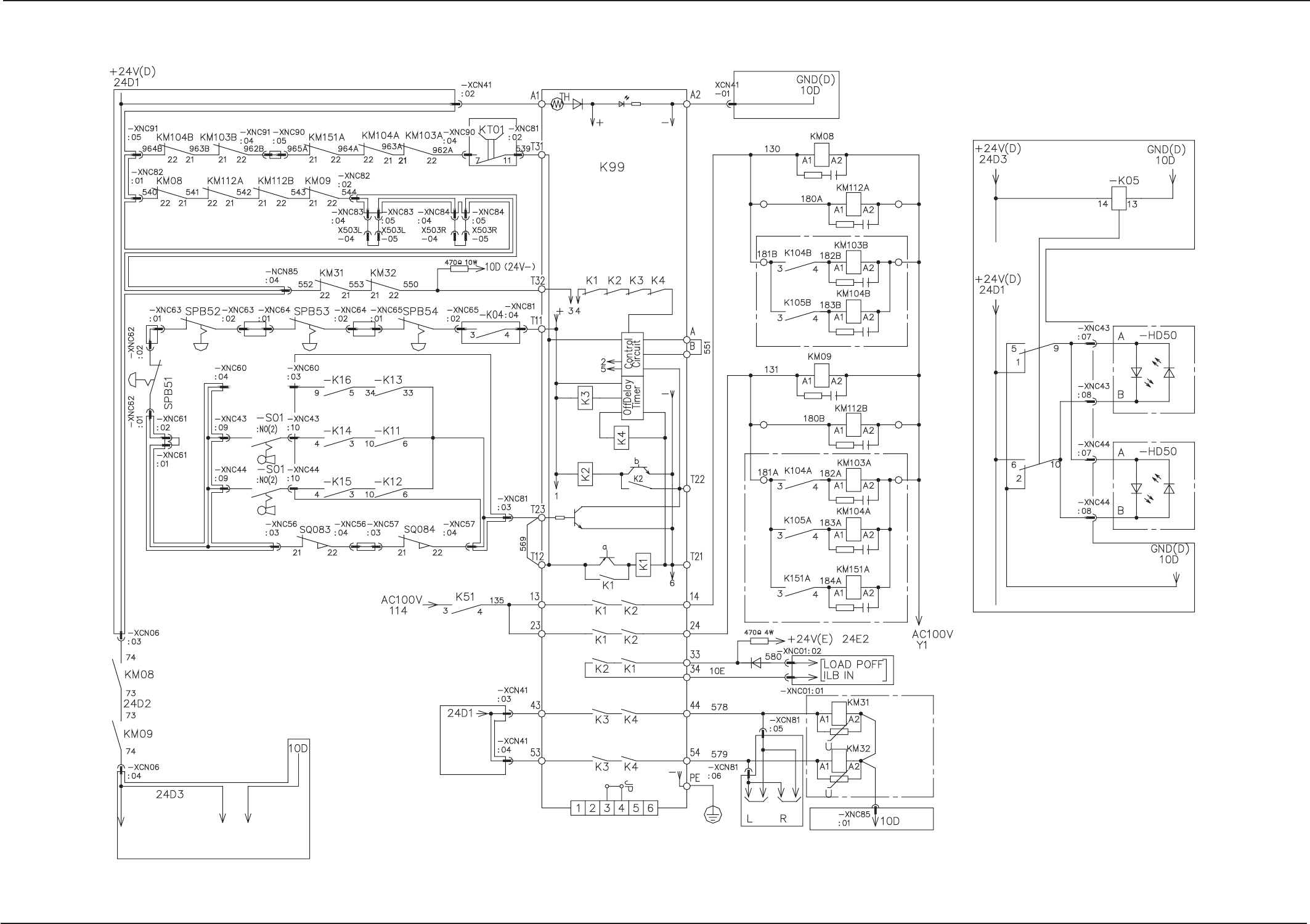
Section5 Electrical Circuit Diagram
Emergency Stop Safety Relay Circuit
0305-001- (M805WB---0004) 5-9 Tg0861-PM-MD
Tray
Tray
G Block
Maintenance Cover
A Detection
Maintenance Cover
B Detection
LB1-Axis Main
Circuit Power
Supply
LB2-Axis Main
Circuit Power
Supply
LA1-Axis Main
Circuit Power
Supply
LA2-Axis Main
Circuit Power
Supply
BPC-Axis Main
Circuit Power
Supply
BM(A) Block
BM(B) Block
Feeder B
(Front Side)
Feeder A
(Rear Side)
BJ Block
BD Block
BE Block
Emergency Stop Safty Relay
BYPASS
SET UP A
SET UP B
Beams A and B
To Safety Relay
Note:
The areas surrounded by the dashed line belong to the relay P.C.B. (UA18 & UA19).
Red
Green
Red
Green
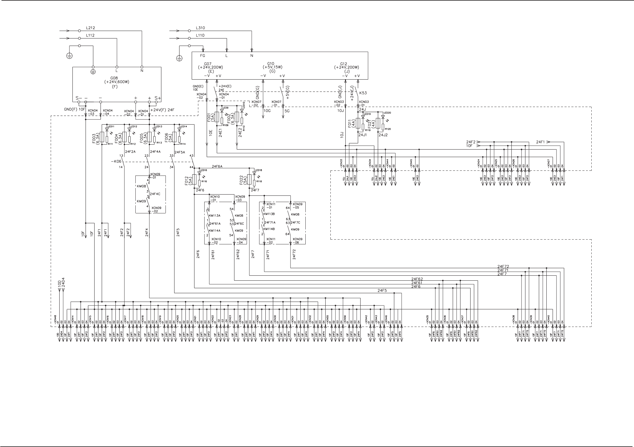
Section5 Electrical Circuit Diagram
DC Power Supply Circuit
0305-001A (M805WB---0005) 5-10 Tg0861-PM-MD
Peripheral
Unit
Peripheral
Unit
Peripheral
Unit
Note: The areas surrounded by the dashed line belong to the relay P.C.B. (UA18 & 19).
To Input/Output I/F Board
(U943) Power Connector (XCN192)
To Operation Box A Tower Light SDS
(CH1) IN&OUT (NODE23,24,27)
Power Connector
To Operation Box B SDS (CH1)
IN&OUT (NODE25,26)
Power Connector
To Feeer Base A1 SDS (CH2)
IN&OUT (NODE11,13,14,15,16)
Power connector
To Feeer Base A2 SDS (CH2)
IN&OUT (NODE19,21,22,23,24)
Power connector
To Feeer Base B1 SDS (CH2)
IN&OUT (NODE27,29,30,31,32)
Power connector
To Feeer Base B2 SDS (CH2)
IN&OUT (NODE35,37,38,39,40)
Power connector
To Tray Feeder L X504L
To Tray Feeder R X504R
Reserved
To Transfer-Related 1 SDS (CH1)
IN (NODE12) Power Connecter
To Up/Down-Stream Unit SDS
(CH1) IN&OUT (NODE22,21)
Power Connector
To Transfer-Related 2 SDS (CH1)
OUT(NODE13) Power Connecter
and Transfer Speed Control Unit(S60)
To Main Body A SDS (CH1)
IN&OUT (NODE15,16)
Power Connector
To Main Body B SDS (CH1)
IN&OUT (NODE17,18)
Power Connector
To Input/Output I/F Board
(U943) Power Connector (XCN191)
To Transfer-Related 1 SDS (CH1)
Out (NODE11) Power Connecter
Reserved
To Converter Board A Connecter
(XNC344)
To Converter Board B Connecter
(XNC348)
LED Lighting Control Board
Connecter (UA08: CN1), Counter
Board (UA23) and P.E.C. Recognition
Lighting Driving SSR (KSSR21,22)
To Feeer Base A1 SDS (CH2)
IN&OUT (NODE11,13,14,15,16)
Power connector
To Feeer Base A2 SDS (CH2)
IN&OUT (NODE19,21,22,23,24)
Power connector
Reserved
To Feeer Base B1 SDS (CH2)
IN&OUT (NODE27.29.30.31.32)
Power connector
To Feeer Base B2 SDS (CH2)
IN&OUT (NODE35,37,38,39,40)
Power connector
Reserved
To Tray Traverse Unit SDS (CH1)
IN (NODE8),
Relay Board (UA03)
To Mechanical Distribution
Board (4) Power Connector
(XCN115,116)
To Mechanical Distribution
Board (3) Power Connector
(XCN112,113)
To Mechanical Distribution
Board (2) Power Connector
(XCN109,110)
To the A head motherboard power
connector (XCN330), the input relay
board (UA03), and the power
connectors (XCN331 and XCN332)
To Control Box Connector XCN92
(To Relay Connector Board UA06)
To the B head motherboard power
connector (XCN370), the input relay
board (UA03), and the power
connectors (XCN371 and XCN372)
To the Transfer-related 2 SDS
(CH1) IN (NODE14) power
connector
24V Load Power Sopply ON
Multi-Power Unit
SLOT 3
SLOT 1
SLOT 4