5OM-1011-002.pdf - 第73页
Section5 Electrical Circuit Diagram 0305-001- (M805WBC--0001) 5-30 Tg0861-PM-MD Control Box Power Supply Circuit SDS Silicon Disk Power Supply 1 T o each external SDS node Relay Connector Board T o the DI/O board T o Pow…
Section5 Electrical Circuit Diagram
0305-001- (M805WBB--0019) 5-29 Tg0861-PM-MD
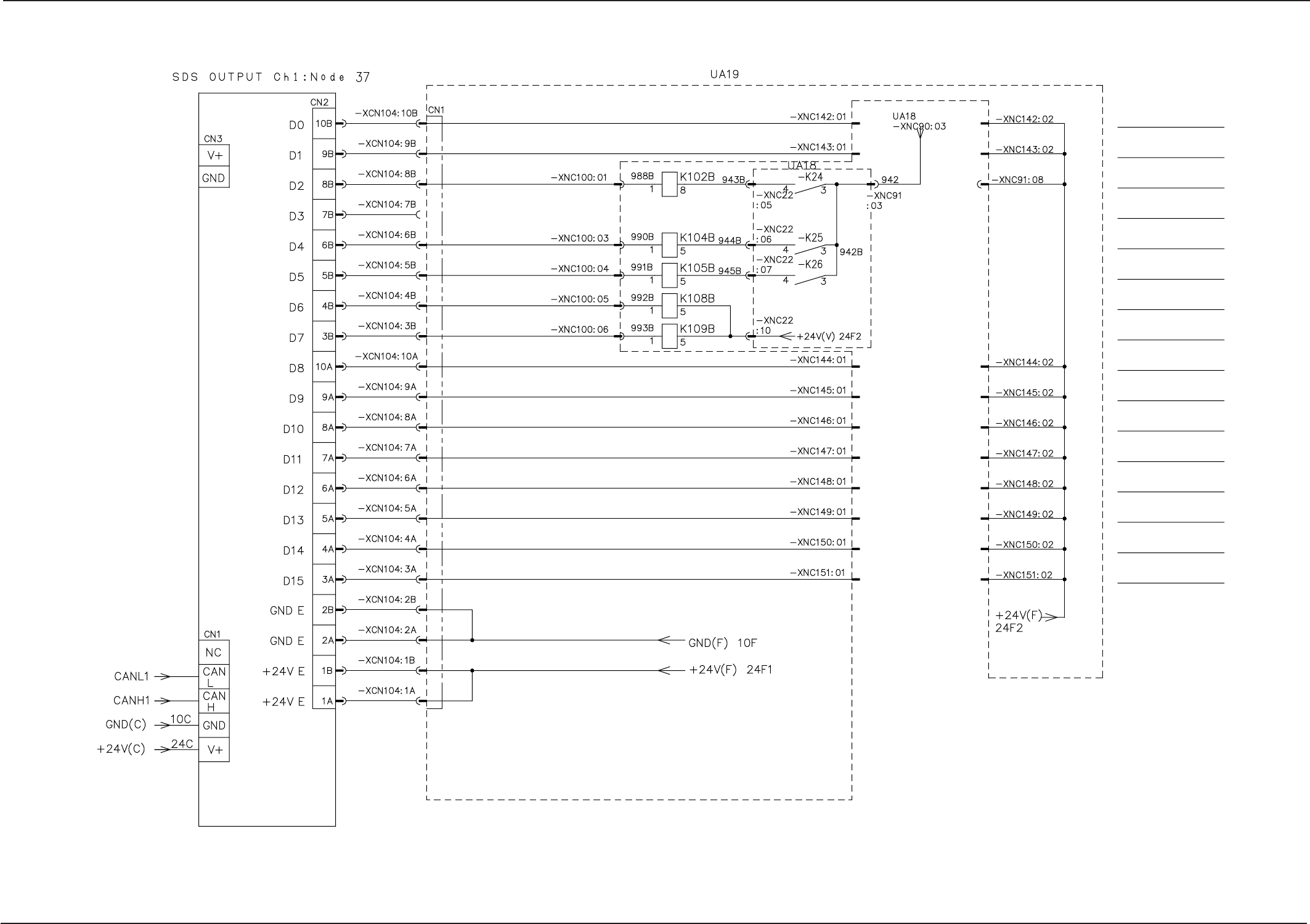
SDS OUT 7
Note:
The area surrounded by the dashed line belongs to the relay P.C.B. (UA18 & UA19).
ZB1-Axis
Power Supply ON
XB/YB-Axis
Power Supply ON
ZB2-Axis
Power Supply ON
LB1-Axis
Power Supply ON
LB1-Axis Brake
Forced Release
LB2-Axis Brake
Forced Release
LB2-Axis
Power Supply ON
Reserved
Reserved
Reserved
Reserved
Reserved
Reserved
Reserved
Reserved
Reserved
Relay P.C.B.
Relay P.C.B.
from

Section5 Electrical Circuit Diagram
0305-001- (M805WBC--0001) 5-30 Tg0861-PM-MD
Control Box Power Supply Circuit
SDS Silicon Disk
Power Supply 1
To each
external
SDS node
Relay Connector Board
To the DI/O
board
To Power
Supply
Section 2
To each
external
SDS node
To the SDS
node in the
control box
Module CH0
Module CH1
To the external
FDD power supply
connector
To the HDD
power supply 2
connector
Option
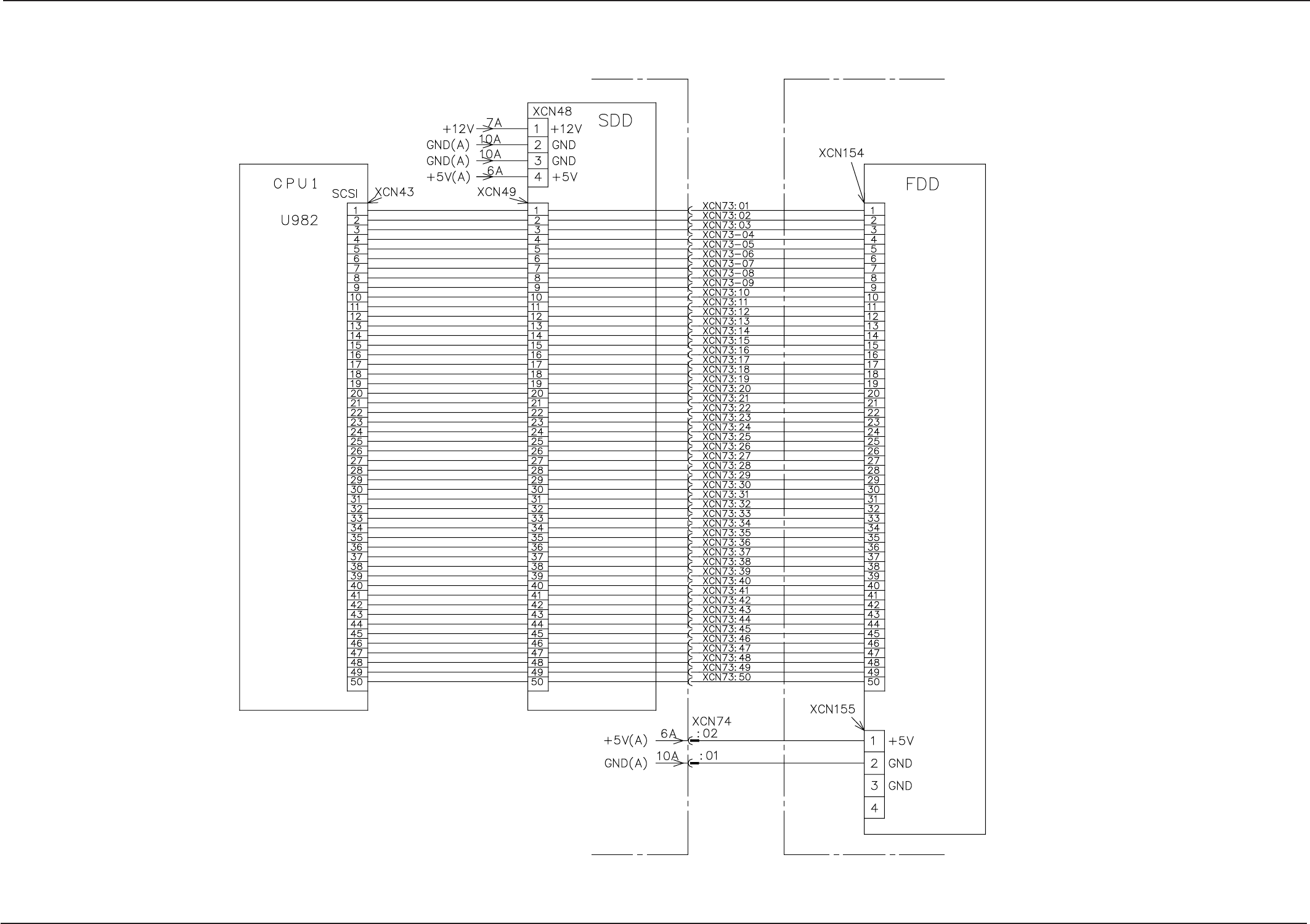
Section5 Electrical Circuit Diagram
0305-001- (M805WBC--0002) 5-31 Tg0861-PM-MD
HDD/FDD Circuit
Inside of Control Box Inside of Conveyor 1 Box
BK Block
Board