APC - 224650 Issue 1.pdf - 第14页
ALL PURPOSE CLAMPING (APC) OVERVIEW 1.2 All Purpose Clamping (APC) Manual Chapter Issue 1 Nov 16 APC Clamping Modules Figure 1-1 Front APC Module - Exploded Over The T op Clamp Assembly Mid Plate Assembly Base Assembly T…
ALL PURPOSE CLAMPING (APC)
OVERVIEW
Chapter Issue 1 Nov 16 All Purpose Clamping (APC) Manual 1.1
CHAPTER 1 ALL PURPOSE CLAMPING (APC)
OVERVIEW
The All Purpose Clamping (APC) system is a substrate management system
that provides multiple clamping and holding options to assist in the processing
of various types of PCB’s that can pass through the DEK screen printer.
The APC system enables clamping of the PCB in three software selectable
modes:
1. Snug Only - the PCB is clamped on the sides, or ends, after first being
flattened into position by the Over The Top (OTT) foils (which are retracted
ahead of the print cycle).
2. Clamp Only - the PCB is clamped using traditional OTT clamping.
3. Snug and Clamp - the PCB is OTT clamped and snugged.
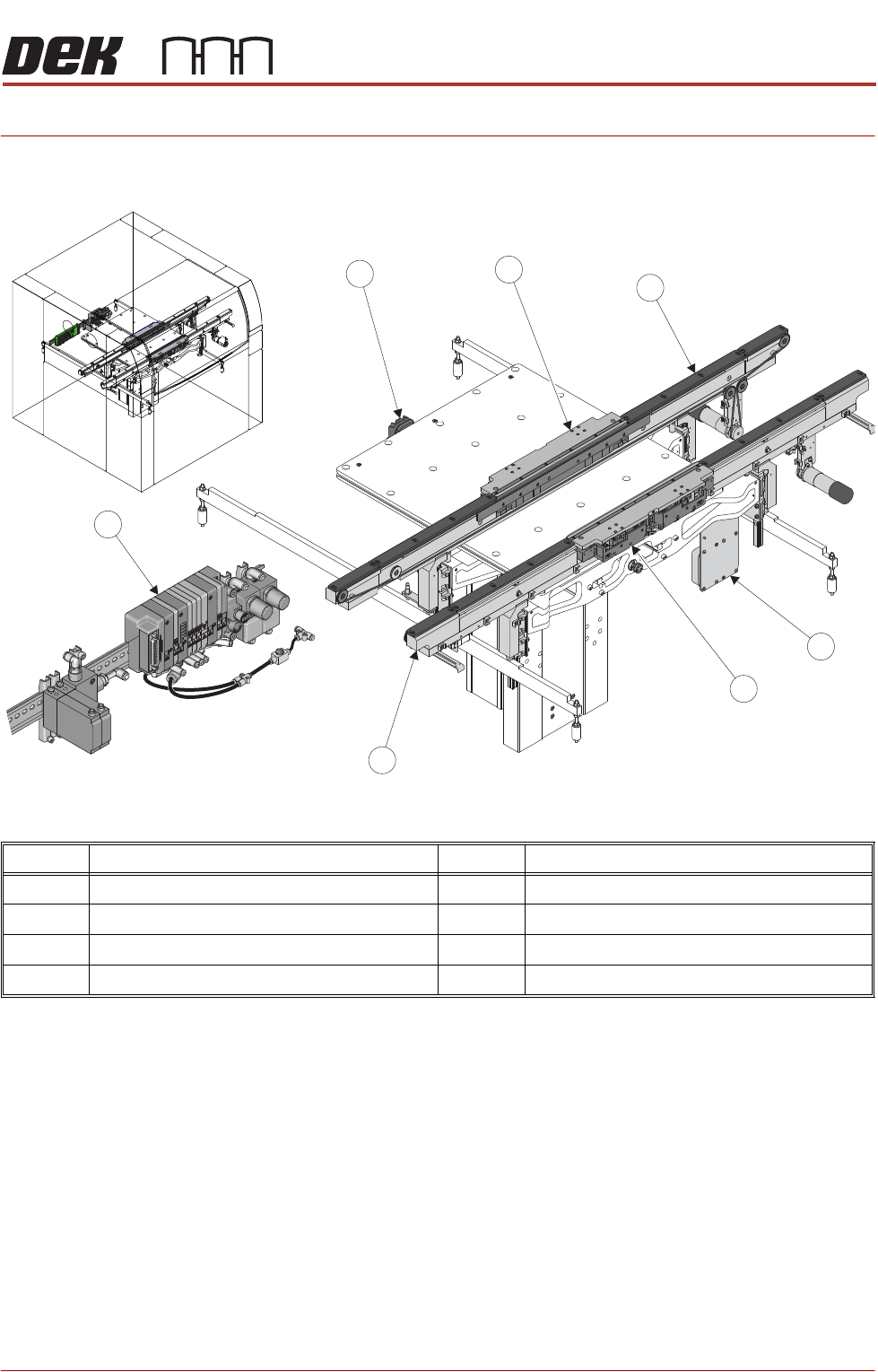
Item Description Item Description
1 Rear APC Module 5 Front Modular Transport Rail (MTR)
2 Rear Modular Transport Rail (MTR) 6 APC Pneumatic Control Rail
3 MTR Circuit Housing 7 Snug/Rail Width Motor
4 Front APC Module
1
4
2
5
3
7
6
ALL PURPOSE CLAMPING (APC)
OVERVIEW
1.2 All Purpose Clamping (APC) Manual Chapter Issue 1 Nov 16
APC Clamping Modules
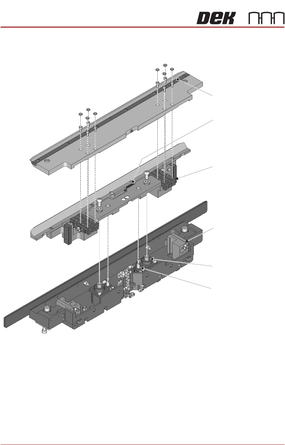
Figure 1-1 Front APC Module - Exploded
Over The Top Clamp
Assembly
Mid Plate Assembly
Base Assembly
Top Clamp Sliding Actuator
(2 positions)
Top Clamp Retract/Extend
Sensor
Pneumatic Z Clamp System
(2 positions)
Ball Spline
(Linear Motion Bearing)
(2 positions)
Pneumatic Cylinder
(Mid Plate Lift)
(2 positions)
NOTE
Pneumatic tubes removed for clarity
Foil Assembly
ALL PURPOSE CLAMPING (APC)
OVERVIEW
Chapter Issue 1 Nov 16 All Purpose Clamping (APC) Manual 1.3
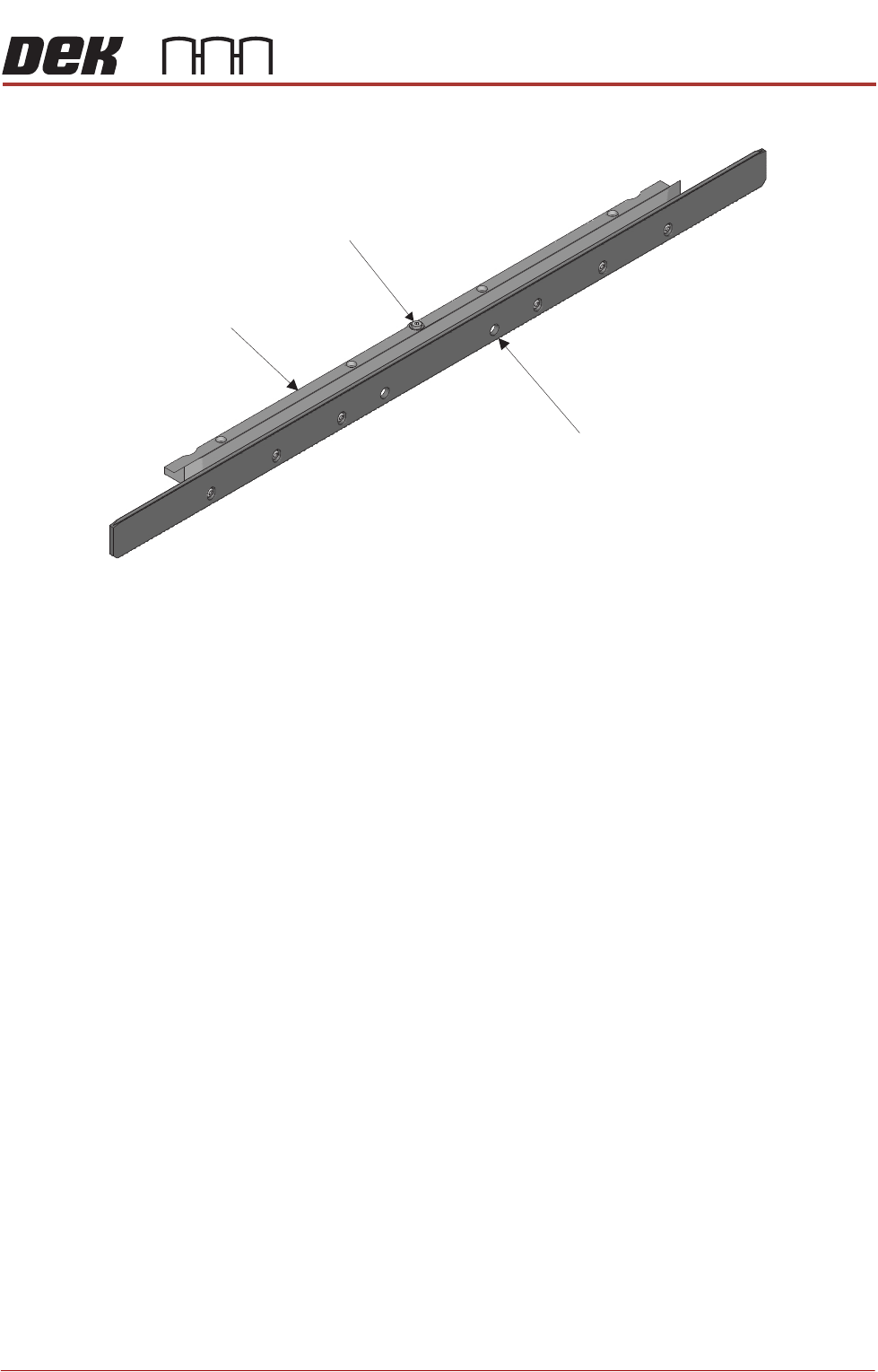
Figure 1-2 Snugger Assembly
Each APC module consists of:
• Board Support and Snug Plate (fixed on the front rail)
• Mid Plate housed in the Machined Body.
• Over the Top Clamp
• Foil Assembly
NOTE
Only items detailed in the Replacement Procedures section of this Chapter are
user serviceable. Any attempt to disassemble parts invalidates all warranty
agreements. Modules must be serviced by a suitably qualified ASM trained
engineer.
Board Support and
Snug Plates
The board support, supports the product while it is in the tooling area of the
machine. The rear rail drives toward the front rail, enabling the rear snug plate
to “snug” the product. If a product is a shape that does not have parallel sides
the snug plate in the rear APC module pivots to accommodate it. On the front
rail this plate is fixed and does not move in the Y axis.
Mid Plate Two clamps (per module) hold the mid plate in place during printing. Print mass
up to 20kg or 200N can take place. The clamps are pneumatically actuated to
open and close.
Over the Top Clamp The over the top clamp provides the top clamping of the product. The top clamp
has a range of movements, up and down using double-acting pneumatic
cylinders and forward and back in the Y-axis using pneumatically actuated
double acting slide tables.
Snug Plate
Board Support
Snug Plate Pivot Point
(Rear Snug Only)