APC - 224650 Issue 1.pdf - 第30页
ALL PURPOSE CLAMPING (APC) ELECTRICAL SCHEMATICS 1.18 All Purpose Clamping (APC) Manual Chapter Issue 1 Nov 16 ELECTRICAL SCHEMA TICS Figure 1-8 APC Schematic Part N2PL3B Part N9SK4A GEMINI OPTION ONL Y M37SK07A Part M37…
ALL PURPOSE CLAMPING (APC)
APC CONTROL
Chapter Issue 1 Nov 16 All Purpose Clamping (APC) Manual 1.17
The amount of pressure used to clamp (top plate lowering onto PCB board) is
controlled by a pneumatic regulator via the machine software parameters, refer
to the APC Software chapter of this manual. The mid plate balance regulator
provides sufficient upward lift to hold the mid plate weight.
NOTE
All three regulators are factory set to achieve the optimum response for the
operation, but the settings are also included in the Adjustments and Settings
section of this chapter for reference.
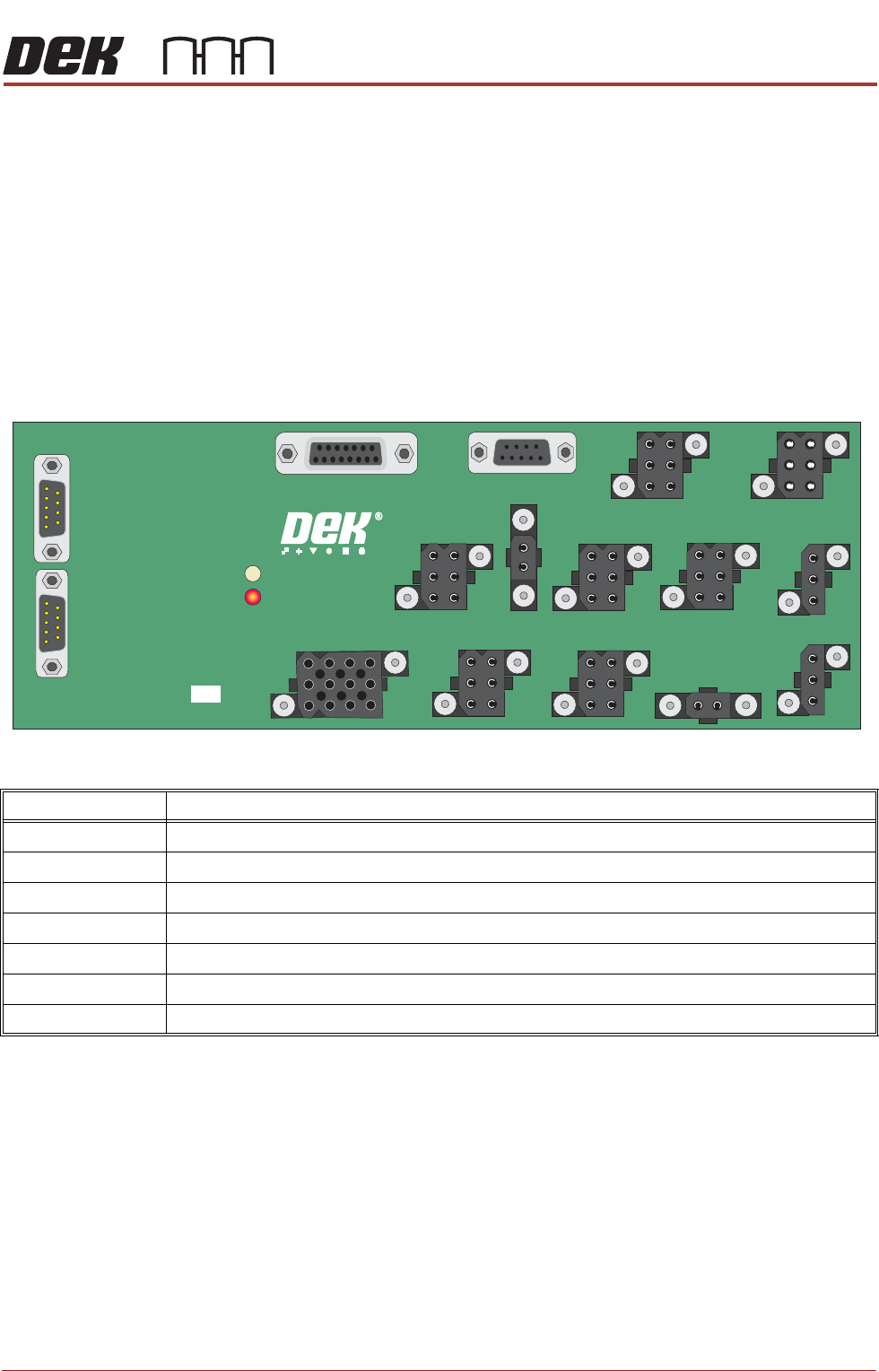
IO Node 5 Node 5 provides the electrical connection to the solenoids, CAN Bus and the
ITV valve.
Figure 1-7 Node 5
Connector Description
N5PL1 +12/+24V Power Input
N5PL2 CAN In
N5PL3 CAN Out
N5SK6 Digital Out 0-4 ~ APC Solenoid Bank
N5SK7 Top Plate Retract Front (Inductive Proximity Sensor)
N5SK8 Top Plate Retract Rear (Inductive Proximity Sensor)
N5SK10 Analogue ~ Clamp Pressure Regulator
NODE 5 OTS & HTC BOARD
198769 ISSUE
N5SK9
N5SK11
N5SK7
N5PL2
N5PL3
N5SK6
N5SK10
N5SK8
N5SK5
N5SK3
N5PL14
N5SK2
N5SK1
N5SK12
N5PL1
N5SK4
ALL PURPOSE CLAMPING (APC)
ELECTRICAL SCHEMATICS
1.18 All Purpose Clamping (APC) Manual Chapter Issue 1 Nov 16
ELECTRICAL SCHEMATICS
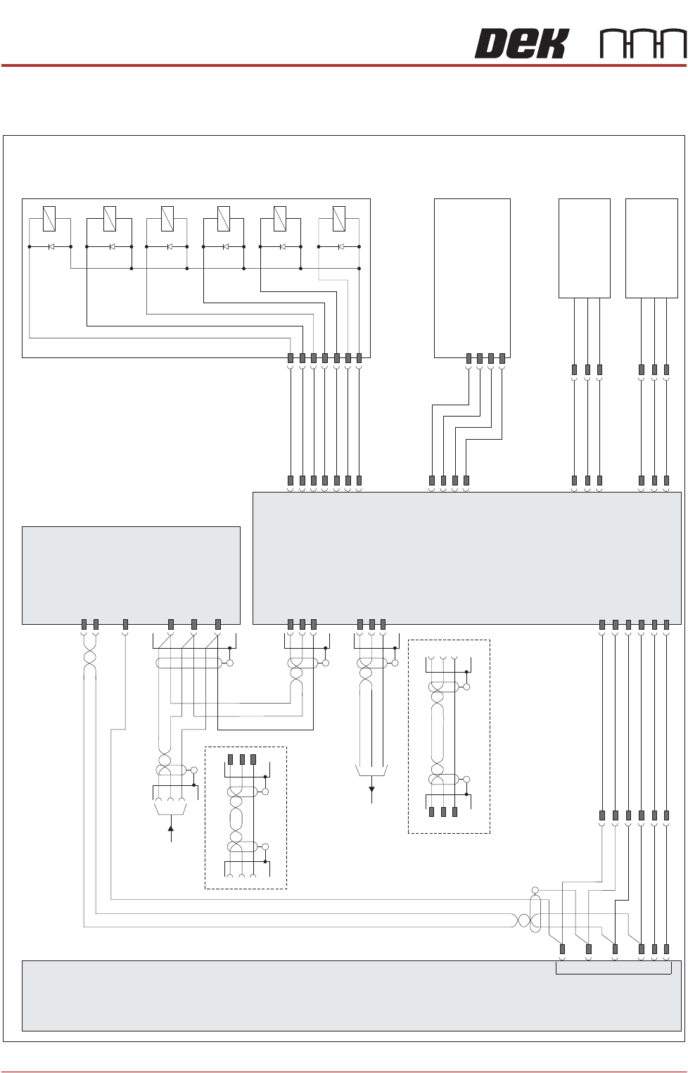
Figure 1-8 APC Schematic
Part N2PL3B
Part N9SK4A
GEMINI OPTION ONLY
M37SK07A
Part M37
Power Supply
Enclosure
M37SK07
+24V US
0V
+24V SW
0V
+12V
0V
APC
Moving Rail Motor
Node 20
N20PL02 - P1
0V
+24V SW
Part N20PL02 - P2B
+24V US
Part N20PL01 - P3
CAN H
CAN L
CAN GND
Part N20SK01
Part N20SK02 - P2B
N20SK02 - P1
Node 5
Part N5PL2
CAN H
CAN L
CAN GND
Part N5SK2
Part N5PL3
CAN H
CAN L
CAN GND
Part N5SK3
Part N5SK3
Part N9PL4
GEMINI OPTION ONLY
Part N2SK3
CAN IN
FROM
NODE 2
CAN OUT
M37PL07
N5SK1 N5PL1
+24V US
0V
+24V SW
+12V
0V
0V
N5SK08
N5PL08
DIG IN 7
+12V
0V
8SE100
TOP PLATE
RETRACT
REAR
INDUCTIVE
PROXIMITY
SWITCH NC
8SK236 8PL236
N5SK07
N5PL07
DIG IN 5
+12V
0V
8SE98
TOP PLATE
RETRACT
FRONT
INDUCTIVE
PROXIMITY
SWITCH NC
8SK235 8PL235
CLAMP PRESSURE
REGULATOR
+24V
PRESSURE DEMAND INPUT
0V
PRESSURE MONITOR OUTPUT
N5SK10
N5PL10
+24V US
ANALOGUE OUT1
0V
ADC IN1
N5SK06
N5PL06
DIG OUT 0
DIG OUT 1
DIG OUT 2
DIG OUT 3
DIG OUT 4
DIG OUT 5
8SOL10
MIDDLE
PLATE UP
8SOL11
MIDDLE
PLATE
DOWN
8SOL12
OVERTOP
PLATE
EXTEND
8SOL13
OVERTOP
PLATE
RETRACT
8SOL14
Z CLAMPS
0V
NOT
USED
ALL PURPOSE CLAMPING (APC)
ELECTRICAL SCHEMATICS
Chapter Issue 1 Nov 16 All Purpose Clamping (APC) Manual 1.19
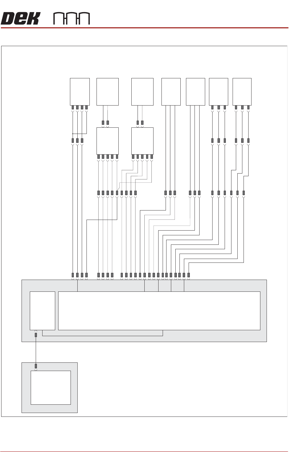
Figure 1-9 Modular Transport Rails Schematic
Machine PC
Motherboard
Machine Control Enclosure
NextMove
Interface Card
X4
NextMove ES
(I/O Node 1)
X5
USB
Board at Left
Sensor (8SE8)
8PL10
8PL04
Sig
+12V
0V
8PL22
M36PL18
Moving Rail
Home (8SE6)
8PL26
M36PL19
+12V
0V
Sig
Rail Lift Right
(8SE4)
+12V
Sig
0V
(L)
8SK23 8PL29
Rear Belt
Drive (8M04)
Dual Speed
Motor
Dual Speed
Motor
Controller
8SK21 8PL29
Front Belt
Drive (8M03)
Dual Speed
Motor
Dual Speed
Motor
Controller
8PL15
Rail Lift Left
(8SE5)
+12V
Sig
0V
8PL12
Board at Right
Sensor (8SE7)
8PL03
Sig
+12V
0V