APC - 224650 Issue 1.pdf - 第68页
ALL PURPOSE CLAMPING (APC) REPLACEMENT PROCEDURES 1.56 All Purpose Clamping (APC) Manual Chapter Issue 1 Nov 16 1 1. Using a 3mm Allen key , remove the cap head screws securing the ballspline assembly to the base assembl…
ALL PURPOSE CLAMPING (APC)
REPLACEMENT PROCEDURES
Chapter Issue 1 Nov 16 All Purpose Clamping (APC) Manual 1.55
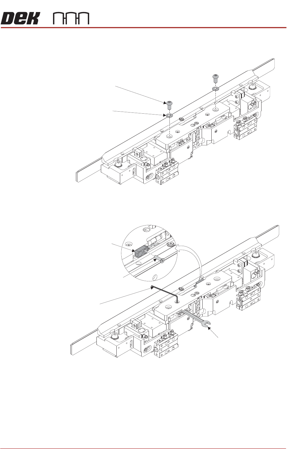
7. Using a 5mm Allen key, remove the socket button head screws and shim
washers from the mid plate.
8. To allow for spanner access, slighty lift the mid plate. Using a 5.5mm A/F
spanner to prevent cylinder rod rotation, remove the lift cylinder shoulder
screws connecting the mid plate to the lift cylinders.
9. Using a 2.5mm Allen key, remove the countersunk screw securing the
sensor to the mid plate. Feed the sensor back through the clearance hole.
10. Remove the mid plate assembly.
Socket Button Head Screw
(2 positions)
Shim Washer
(2 position)
Allen Key
5.5 A/F Spanner
Sensor
Countersunk Screw
ALL PURPOSE CLAMPING (APC)
REPLACEMENT PROCEDURES
1.56 All Purpose Clamping (APC) Manual Chapter Issue 1 Nov 16
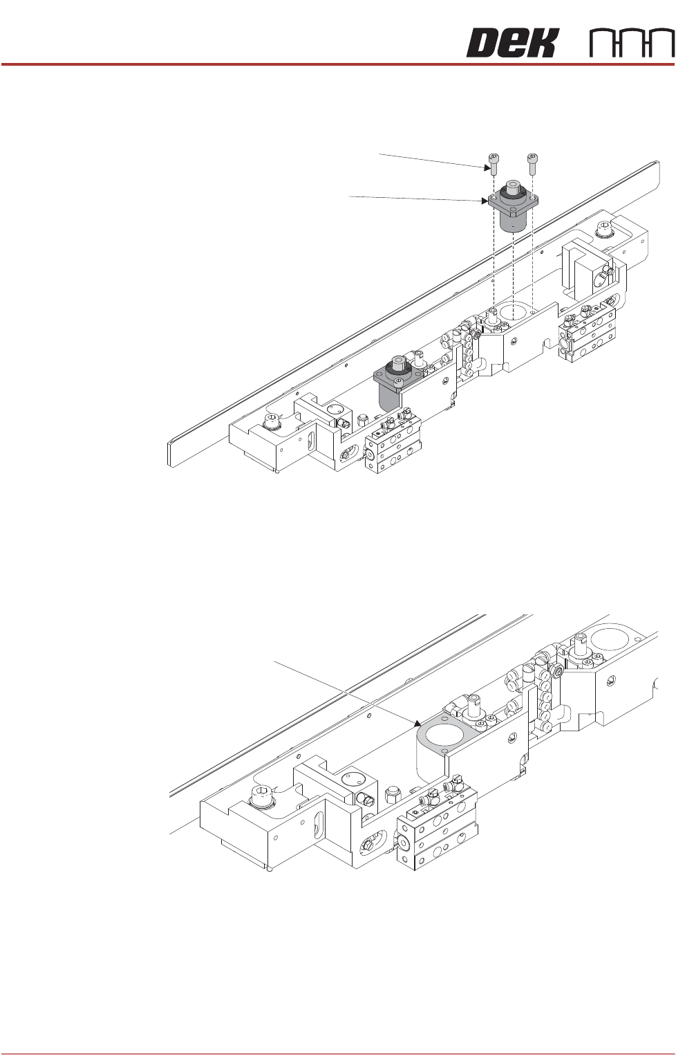
11. Using a 3mm Allen key, remove the cap head screws securing the ballspline
assembly to the base assembly.
12. Remove the ballspline assembly.
13. Repeat Steps 11 to 12 for the other ballspline assembly.
Replace 1. Using IPA wipes, clean the lift cylinder mounting faces on the base assem-
bly.
Ballspline Assembly
Cap Head Screw
(2 positions)
Ballspline Assembly
Mating Face
ALL PURPOSE CLAMPING (APC)
REPLACEMENT PROCEDURES
Chapter Issue 1 Nov 16 All Purpose Clamping (APC) Manual 1.57
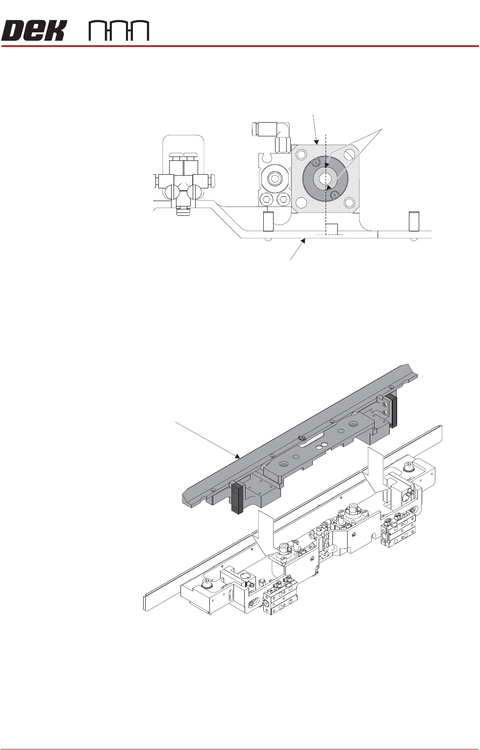
2. Install the ballspline assembly, ensuring the splines are orientated 90° to the
rear face of the base assembly.
3. Using a 3mm Allen key, secure the ballspline assembly to the base assem-
bly with 2 cap head screws.
4. Install the mid plate assembly.
5. Feed the sensor back through the clearance hole. Secure the sensor to the
mid plate using a 2.5mm Allen key and countersunk screw .
6. With the mid plate in the lowered position, install the 2 shouldered screws
and tighten until the cylinder rods start rotating.
Top View Showing Ball Spline Assembly Orientation
Ball Spline Assembly
Splines/Grooves
Rear of Base Assembly
90°
Midplate
Assembly