APC - 224650 Issue 1.pdf - 第55页
ALL PURPOSE CLAMPING (APC) REPLACEMENT PROCEDURES Chapter Issue 1 Nov 16 All Purpose Clamping (APC) Manual 1.43 Board Clamp Foil Replacement W A RNING BOARD CLAMPS. EXTREME CA RE MUST BE EXERCISED W HEN WORKING IN THE TO…
ALL PURPOSE CLAMPING (APC)
REPLACEMENT PROCEDURES
1.42 All Purpose Clamping (APC) Manual Chapter Issue 1 Nov 16
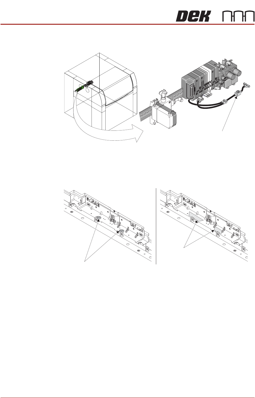
22. Use the isolator switch valve to remove the air supply from the APC
modules.
23. Locate the ball spline bores on the underside of the APC module. To prevent
the possibility of the shafts dropping out in the middle of a replacement
procedure, apply two lengths of masking tape to cover the bores.
After Replacement
Procedures
After any replacement procedure has been carried out (not including board
clamp foils if they are the only replacement), the following Adjustment and
Settings procedures should be carried out:
1. Remove masking tape from the underside of the APC modules.
2. When product width is set to 250mm the distance between the rails (meas-
ured at the snug bar centre) should be between 250.48mm and 250.52mm.
If the distance between the rails is outside these parameters, then carry out
the Home Position Rail Width and Board Guide Setting procedure in the
Adjustments and Settings section of this chapter.
3. Carry out the Board Transit Clearance Check procedure in the Adjustments
and Settings section of this chapter.
Isolator Switch Valve
Location of APC Pneumatic Manifold
View on Underside of APC Module
(Wiring Removed for Clarity)
Ball Spline Bore
(2 positions)
Masking Tape
ALL PURPOSE CLAMPING (APC)
REPLACEMENT PROCEDURES
Chapter Issue 1 Nov 16 All Purpose Clamping (APC) Manual 1.43
Board Clamp Foil Replacement
WARNING
BOARD CLAMPS. EXTREME CARE MUST BE EXERCISED WHEN WORKING IN
THE TOOLING AREA OF THE MACHINE TO AVOID INJURY. THE FOILS ON THE
FRONT AND REAR BOARD CLAMPS ARE VERY SHARP.
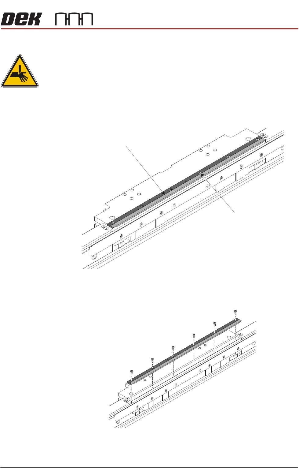
Remove 1. Ensure the Prepare for Replacement procedure has been completed.
2. Using a 2.5mm Allen key, remove the board clamp foil securing screws and
remove the board clamp foil assembly.
Replace 1. Place the replacement board clamp foil assembly in position on the top
plate, fasten to the APC module using the six off replacement securing
screws supplied with the replacement board clamp foil.
Board Clamp Foil
Board Clamp Foil
Securing Screws
(6 off)
View on Rear APC Module
View on Rear APC Module
ALL PURPOSE CLAMPING (APC)
REPLACEMENT PROCEDURES
1.44 All Purpose Clamping (APC) Manual Chapter Issue 1 Nov 16
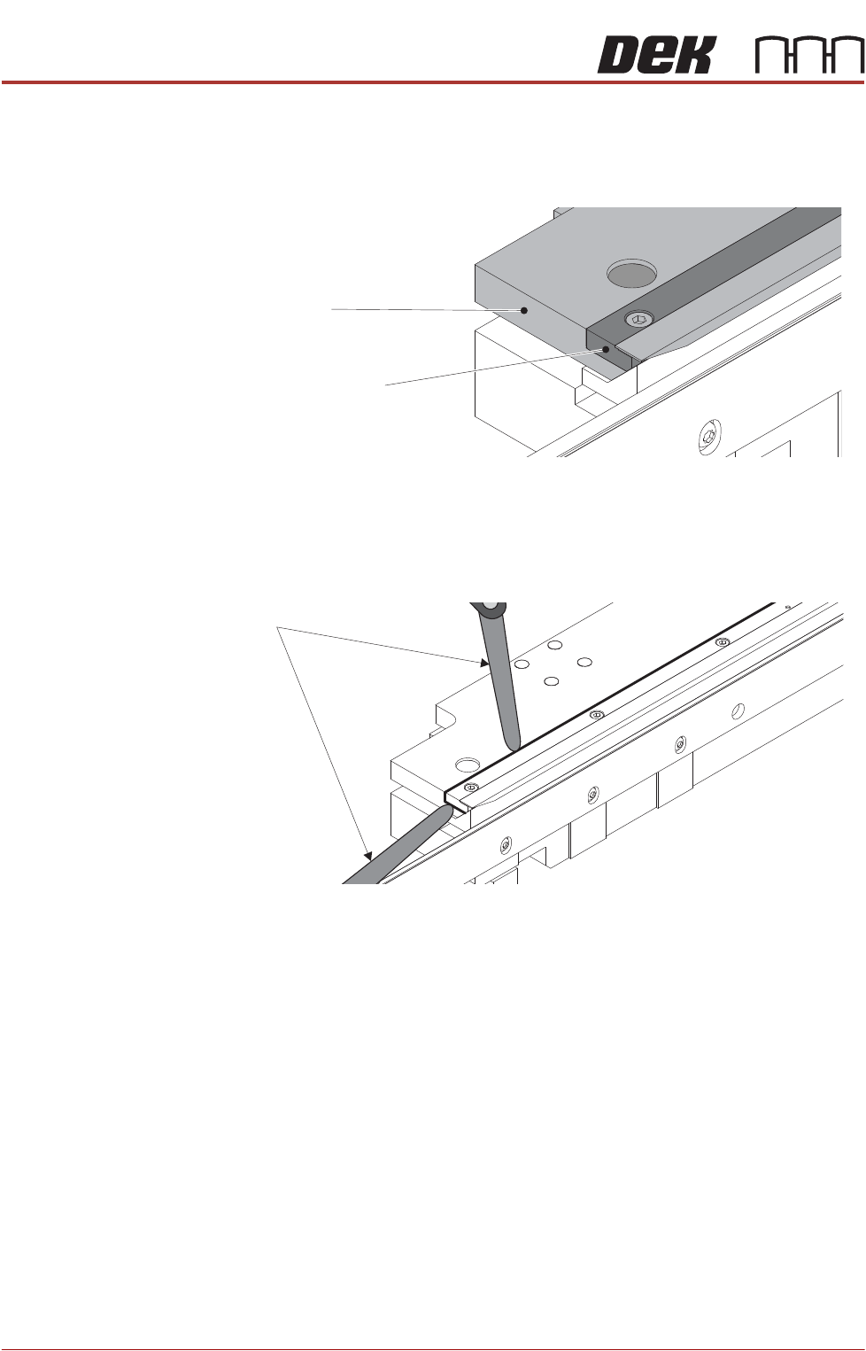
2. Check that the foil assembly is fitted fully home on the top plate:
a. Ensure the ends of the foil assembly are flush with the ends of the top
plate.
b. Check that a 0.05mm feeler gauge will not go between the foil assembly
and the top plate. Perform check in multiple locations along the length,
and at the ends.
View on Ends of Top Plate and Foil Assembly
Top Plate End
Foil Assembly End
Feeler Gauge