APC - 224650 Issue 1.pdf - 第67页
ALL PURPOSE CLAMPING (APC) REPLACEMENT PROCEDURES Chapter Issue 1 Nov 16 All Purpose Clamping (APC) Manual 1.55 7. Using a 5mm Allen ke y , remove the socket button head scre ws and shim washers from the mid plate. 8. T …
ALL PURPOSE CLAMPING (APC)
REPLACEMENT PROCEDURES
1.54 All Purpose Clamping (APC) Manual Chapter Issue 1 Nov 16
9. Install the board clamp foil as detailed in Board Clamp Foil Replacement -
Replace.
10. Complete the After Replacement Procedures.
Ballspline
Assembly
Replacement
There are two mid plate ballspline assemblies per APC module, if replacement
is required then both assemblies in a module should be replaced as a pair.
Remove 1. Ensure the Prepare for Replacement procedure has been completed.
2. Remove the board clamp foil, as detailed in Board Clamp Foil Replacement
- Remove.
3. Remove the top plate, as detailed in Top Plate Replacement - Remove.
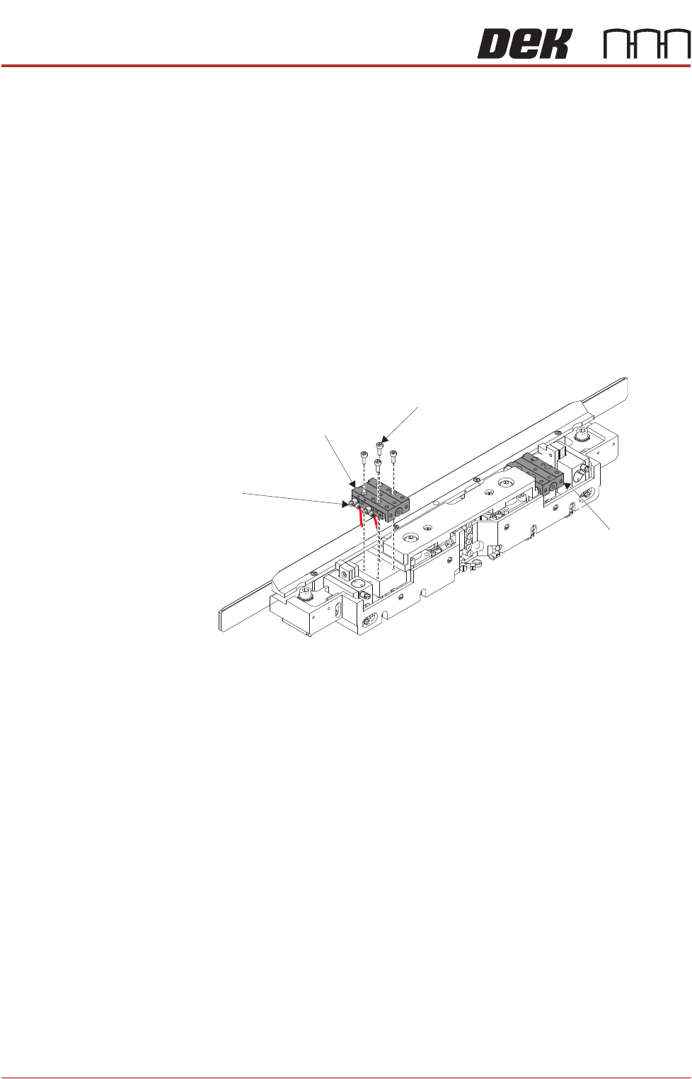
4. Using a 2.5mm Allen key, remove the cap head screws from the first slide
table. Leave the pneumatic elbow fittings attached to the slide table.
5. Move the slide table from its mounting, and allow it to hang over the rear of
the module, the weight being supported by the still attached pneumatic
fittings.
6. Repeat Steps 4 to 5 for the other slide table.
Slide Table
Cap Head Screw
(4 positions)
Pneumatic Elbow Fittings
(2 positions)
Slide Table
ALL PURPOSE CLAMPING (APC)
REPLACEMENT PROCEDURES
Chapter Issue 1 Nov 16 All Purpose Clamping (APC) Manual 1.55
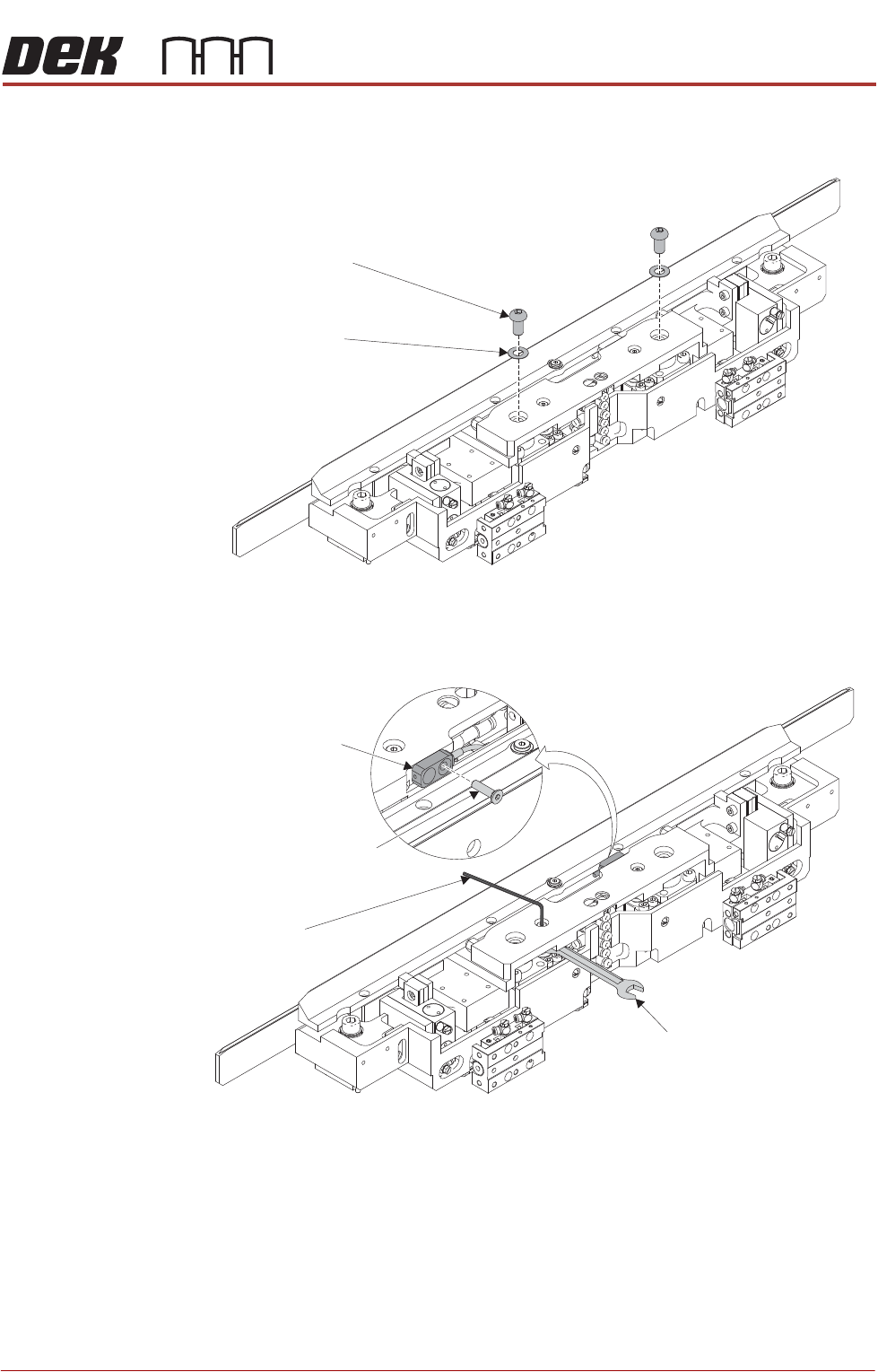
7. Using a 5mm Allen key, remove the socket button head screws and shim
washers from the mid plate.
8. To allow for spanner access, slighty lift the mid plate. Using a 5.5mm A/F
spanner to prevent cylinder rod rotation, remove the lift cylinder shoulder
screws connecting the mid plate to the lift cylinders.
9. Using a 2.5mm Allen key, remove the countersunk screw securing the
sensor to the mid plate. Feed the sensor back through the clearance hole.
10. Remove the mid plate assembly.
Socket Button Head Screw
(2 positions)
Shim Washer
(2 position)
Allen Key
5.5 A/F Spanner
Sensor
Countersunk Screw
ALL PURPOSE CLAMPING (APC)
REPLACEMENT PROCEDURES
1.56 All Purpose Clamping (APC) Manual Chapter Issue 1 Nov 16
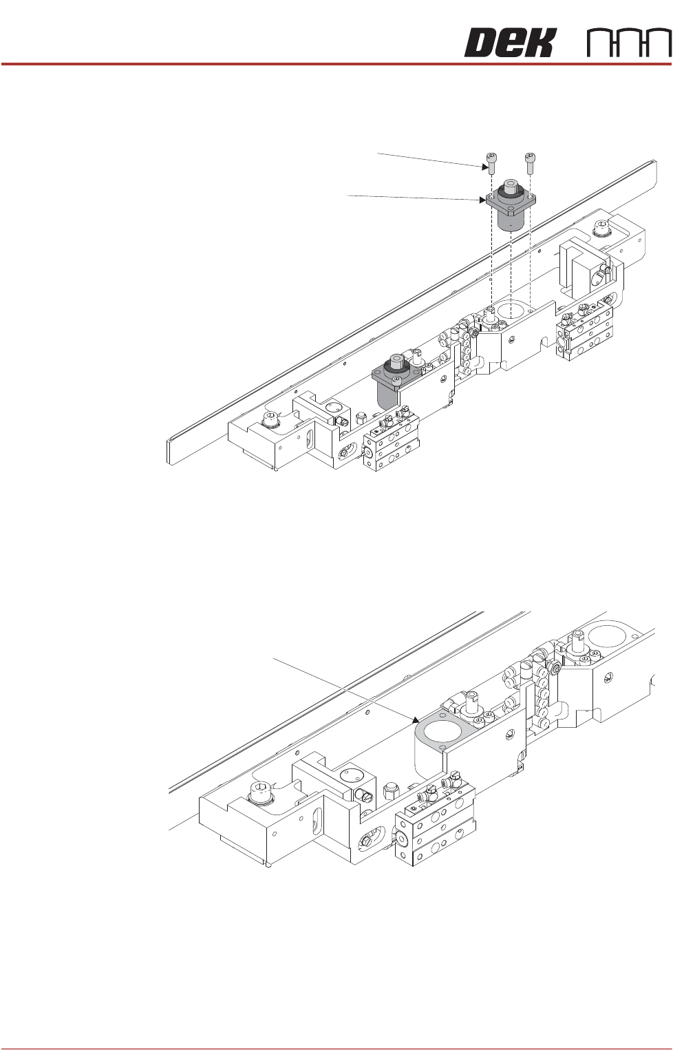
11. Using a 3mm Allen key, remove the cap head screws securing the ballspline
assembly to the base assembly.
12. Remove the ballspline assembly.
13. Repeat Steps 11 to 12 for the other ballspline assembly.
Replace 1. Using IPA wipes, clean the lift cylinder mounting faces on the base assem-
bly.
Ballspline Assembly
Cap Head Screw
(2 positions)
Ballspline Assembly
Mating Face