APC - 224650 Issue 1.pdf - 第78页
ALL PURPOSE CLAMPING (APC) REPLACEMENT PROCEDURES 1.66 All Purpose Clamping (APC) Manual Chapter Issue 1 Nov 16 Zimmer Clamp Replacement There are two clamps per APC mod ule, if replacement is required then both clamps i…
ALL PURPOSE CLAMPING (APC)
REPLACEMENT PROCEDURES
Chapter Issue 1 Nov 16 All Purpose Clamping (APC) Manual 1.65
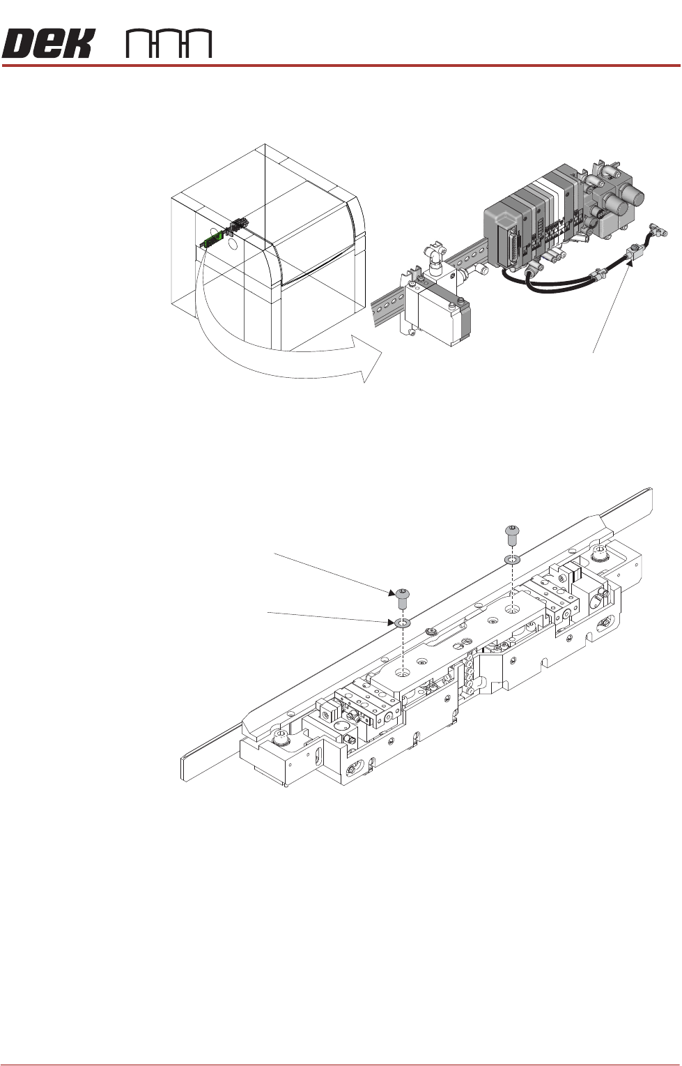
14. Use the isolator switch valve to reinstate the air supply to the APC modules.
Check that the zimmer clamps have energised.
15. Using a 5mm Allen key, reinstall the socket button head screws and shim
washers that attach the mid plate to the ball spline assemblies.
16. Use the isolator switch valve to isolate the air supply to the APC modules.
Disconnect the up-stream hose from the isolator switch to allow any residual
pressure in the system to vent. Reconnect the up-stream hose.
17. Ensure that the mid plate assembly has free movement. Lift the assembly
and allow to drop, checking that it drops under its own weight back to its
original position.
18. Install the top plate as detailed in Top Plate Replacement - Replace.
19. Install the board clamp foil as detailed in Board Clamp Foil Replacement -
Replace.
20. Complete the After Replacement Procedures.
Isolator Switch Valve
Location of APC Pneumatic Manifold
Socket Button Head Screw
(2 positions)
Shim Washer
(2 position)
ALL PURPOSE CLAMPING (APC)
REPLACEMENT PROCEDURES
1.66 All Purpose Clamping (APC) Manual Chapter Issue 1 Nov 16
Zimmer Clamp
Replacement
There are two clamps per APC module, if replacement is required then both
clamps in a module should be replaced as a pair.
Remove 1. Ensure the Prepare for Replacement procedure has been completed.
2. Remove the board clamp foil, as detailed in Board Clamp Foil Replacement
- Remove.
3. Remove the top plate, as detailed in Top Plate Replacement - Remove.
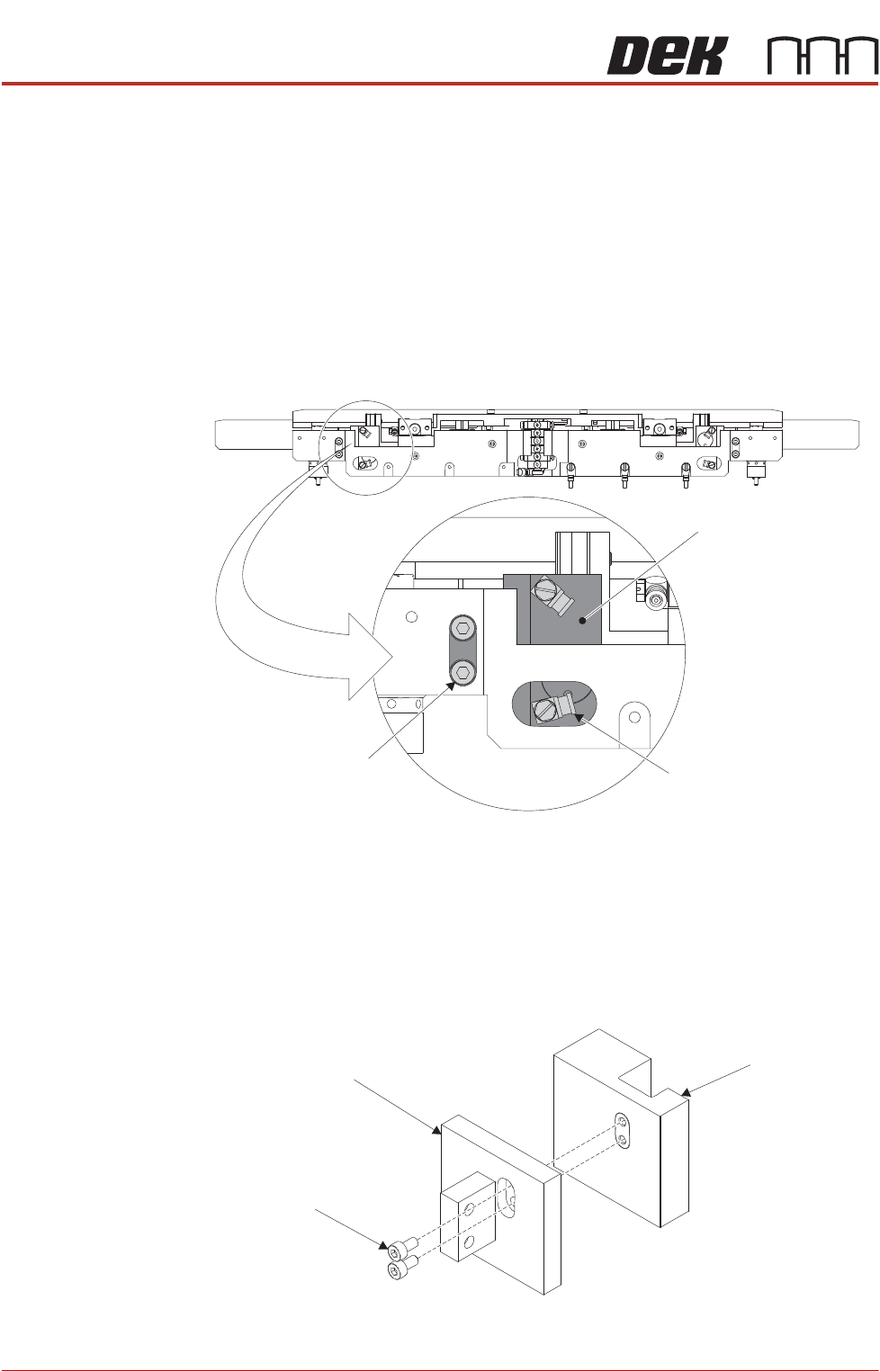
4. Using a flat bladed screwdriver, remove the pneumatic elbow fittings.
NOTE
Marking the elbow fittings A and B will aid during reassembly. Also make a
note of the orientation.
5. Using a 2.5mm Allen key, remove the clamp mounting block retaining cap
head screws.
6. Remove the clamp and clamp mounting block assy.
7. Using a 2mm Allen key, remove the cap head screws that secure the clamp
to the clamp mounting block.
8. Repeat Steps 4 to 7 for the other clamp.
Pneumatic Elbow Fitting
(2 positions)
Cap Head Screw
(2 positions)
Clamp and Clamp
Mounting Block Assy
Clamp Mounting Block
Cap Head Screws
Clamp
ALL PURPOSE CLAMPING (APC)
REPLACEMENT PROCEDURES
Chapter Issue 1 Nov 16 All Purpose Clamping (APC) Manual 1.67
Replace 1. Prepare new clamp, by cleaning all faces with IPA wipes to ensure transport
grease has been removed. Particular attention should given to the piston
face.
2. Using a 1.5mm Allen key, remove the protective blanking screw from port B
and the venting screw from port A on the clamp.
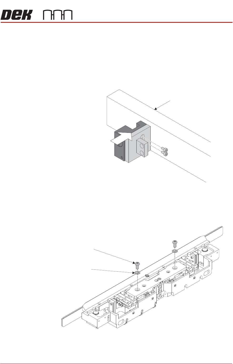
3. Using a flat work surface and square block, set the mounting block edges
flush with the clamp edges. Secure the clamp to the mounting block using
a 2mm Allen key and cap head screws.
4. Repeat Steps 1 to 3 for the other clamp assembly.
5. Using a 5mm Allen key, remove the socket button head screws and shim
washers from the mid plate. Apply thread lock compound to the screws, and
refit loosely so the mid plate is free to move.
Square Block
Socket Button Head Screw
(2 positions)
Shim Washer
(2 position)